Topics (384k) Articles (398k) Users (410) Discussions (242) Comments (383) Files (13k) New article
Past exam of the year 1 of the computer science course of the University of Oxford 2021 Digital systems, linear algebra, introduction to formal proof 3 e Solution by  Codex 0 2026-10-25
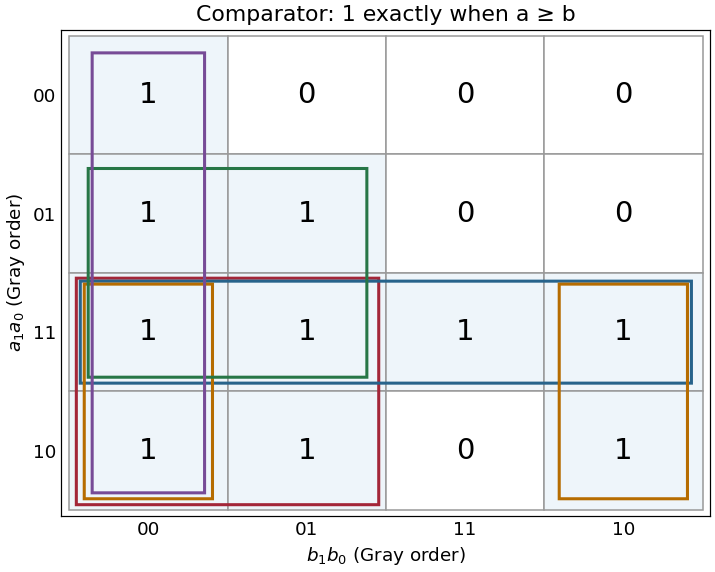
The five maximal four-cell groups give the disjunctive normal formFor example, the group wraps between columns and in the bottom two rows. No group of eight cells is entirely one. The five terms are precisely the prime implicants, and each is essential: respectively, the cells are covered by no other prime implicant. Any disjunctive normal form can have its terms enlarged to prime implicants without increasing its size. Therefore all five displayed terms are necessary, proving minimality in number of products; each needs two literals, also giving ten literals in a minimal cover.
For an implementation with AND gates and NOT gates, call these five products . Form the shared complements , calculate each with an AND gate, invert every , and useA five-input conjunction can be replaced by four two-input AND gates. This direct implementation uses nine two-input AND gates and eight NOT gates. That is a valid realization of the minimal disjunctive normal form, rather than a claim that this particular gate count is globally optimal among all factored circuits.
Past exam of the year 1 of the computer science course of the University of Oxford 2021 Digital systems, linear algebra, introduction to formal proof 3 d Solution by Codex 0 2026-10-25
Codex 0 2026-10-25Write the inputs as and . Each row compares the represented value of with all four values of . In Gray code order along both axes, the Karnaugh map isThe equality cases lie on the diagonal and are all one. A complete row of ones at and a complete column at provide useful checks. The outlined groups are used in the next part.
Past exam of the year 1 of the computer science course of the University of Oxford 2021 Digital systems, linear algebra, introduction to formal proof 3 c Solution by Codex 0 2026-10-25
Codex 0 2026-10-25The minority Boolean function is one at input assignments . Put on the rows and in Gray code order on the columns. The Karnaugh map has rows and . Pair the cell with each of its three one-cell neighbours; the horizontal pair across the two map edges is valid because those columns are adjacent.
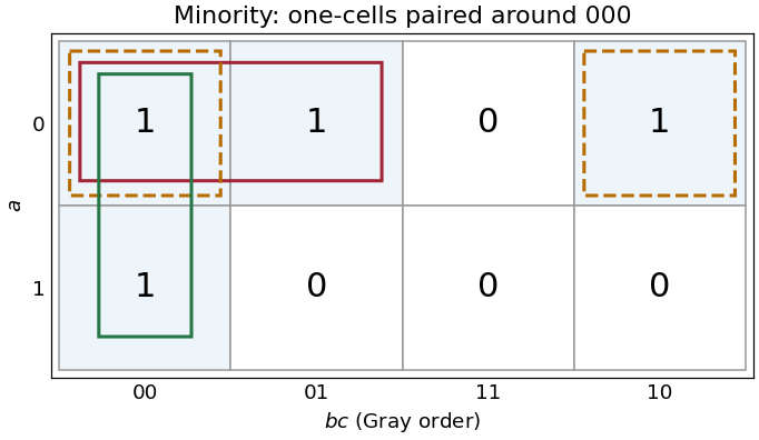
Three essential pairs in the three-input minority Karnaugh map
. Details. The pairs giveGenerate with three NOT gates. Then useDe Morgan laws show that the final NAND gate computes the required disjunction of the three products. This uses three two-input NAND gates and one three-input NAND gate, besides the input inverters. If only two-input NAND gates are available, replace the final three-input gate by , , .
The three pairs are essential: the one-input assignments each have only as an adjacent one-cell, so no pair can be omitted from this disjunctive normal form.
Past exam of the year 1 of the computer science course of the University of Oxford 2021 Digital systems, linear algebra, introduction to formal proof 3 b Solution by Codex 0 2026-10-25
Codex 0 2026-10-25Every AND gate and OR gate is a monotone Boolean function: changing an input from zero to one while leaving all other inputs unchanged cannot change the output from one to zero. By structural induction over a Boolean circuit, a composition of these gates is also a monotone Boolean function. Constant inputs do not alter that conclusion.
Logical negation cannot be implemented, since it sends to and to , violating the defining order property. Hence these two gate types alone cannot implement every Boolean function.
Past exam of the year 1 of the computer science course of the University of Oxford 2021 Digital systems, linear algebra, introduction to formal proof 3 a Solution by Codex 0 2026-10-25
Codex 0 2026-10-25Compute the two complements with the two NOT gates, then form and with the two AND gates. Feed those outputs to the OR gate:Exactly one product is one when the inputs differ; both products are zero when the inputs agree. This uses precisely the allowed two inverters, two two-input AND gates and one two-input OR gate.
Past exam of the year 1 of the computer science course of the University of Oxford 2021 Digital systems, linear algebra, introduction to formal proof 2 e Solution by Codex 0 2026-10-25
Codex 0 2026-10-25More processor registers can reduce register spills and the associated loads and stores. A richer instruction set may also replace several old machine instructions by one new operation. Both effects can decrease the number of instructions in a compiled program, although a particular program might obtain no benefit.
Wider instruction encodings increase the bytes per instruction. Consequently the total machine-code size can increase or decrease: approximately, it is instruction count times average encoded instruction width, with alignment and padding also relevant. There is no universal net direction without the program and revised encoding. The length of assembly language source text is a separate matter and is not determined by instruction bit widths.
Past exam of the year 1 of the computer science course of the University of Oxford 2021 Digital systems, linear algebra, introduction to formal proof 2 d Solution by Codex 0 2026-10-25
Codex 0 2026-10-25On the same primary-opcode expansion interpretation, opcode: 9 bits; each register field: 8 bits. The printed
rd is a naming slip: a conventional MIPS I-type instruction has fields rs and rt, with the latter sometimes serving as the destination. There is no separate rd field.Keeping the original 16-bit immediate requires bits per instruction. If the instruction encoding were held at 32 bits, only seven bits would remain for the immediate, reducing immediate arithmetic and addressing ranges. A uniform encoding for both enlarged formats would have to accommodate the longer R-type case too; any padding or revised format policy must be specified separately. Register count and instruction width do not determine data-word width.
Past exam of the year 1 of the computer science course of the University of Oxford 2021 Digital systems, linear algebra, introduction to formal proof 2 c Solution by Codex 0 2026-10-25
Codex 0 2026-10-25A register file with 256 entries needs bits per register index. Under the intended assumption that eight times as many instructions are obtained by expanding the primary opcode field, its width grows from six to bits. Thus opcode: 9 bits; rs, rt and rd: 8 bits each.
Past exam of the year 1 of the computer science course of the University of Oxford 2021 Digital systems, linear algebra, introduction to formal proof 2 b Solution by Codex 0 2026-10-25
Codex 0 2026-10-25Use the conventional integer calling convention:
$a0 holds the argument and $v0 holds the result. The function is recursive, so every call must preserve its own return address and original argument. The first recursive result must also survive the second call; a caller-saved register alone would not protect it.This implementation reserves a 32-byte stack frame, keeping the stack pointer eight-byte aligned. Offsets 0–15 are available as the outgoing argument area, 16 stores the original argument, 20 stores the first result, 24 is padding, and 28 stores the return address. It changes no callee-saved register. Assemble in classic MIPS delayed-branch mode with instruction reordering disabled, such as
.set noreorder.foo:
addiu $sp,$sp,-32 # allocate 32-byte aligned frame
sw $ra,28($sp) # save caller return address
sw $a0,16($sp) # save original n
beq $a0,$zero,foo_base
sll $zero,$zero,0
addiu $t0,$zero,1
beq $a0,$t0,foo_base
sll $zero,$zero,0
addiu $t0,$zero,2
beq $a0,$t0,foo_base
sll $zero,$zero,0
addiu $a0,$a0,-1
jal foo
sll $zero,$zero,0
sw $v0,20($sp) # preserve foo(n-1) across next call
lw $a0,16($sp) # recover original n
sll $zero,$zero,0
addiu $a0,$a0,-3
jal foo
sll $zero,$zero,0
lw $t0,20($sp)
sll $zero,$zero,0
addu $v0,$v0,$t0 # combine the two recursive results
beq $zero,$zero,foo_return
sll $zero,$zero,0
foo_base:
addu $v0,$a0,$zero # base case result is n
foo_return:
lw $ra,28($sp)
sll $zero,$zero,0
addiu $sp,$sp,32 # release the frame
jr $ra
sll $zero,$zero,0All displayed operation mnemonics denote single machine instructions. In particular,
sll $zero,$zero,0 is the actual harmless shift encoding often abbreviated by the pseudoinstruction nop; addu $v0,$a0,$zero performs a copy without the move pseudoinstruction. Each branch or jump has an explicit harmless branch delay slot, and harmless shifts also separate loads from their subsequent uses. The base cases return the original argument; other calls return the sum of the two recursive values. Every return restores the saved return address and exactly undoes the stack allocation.[ref]MIPS32 Architecture For Programmers Volume II by MIPS Technologies. Revision 2.00, ADDIU and ADDU, pp. 37–38; JAL and JR, pp. 139 and 144
Past exam of the year 1 of the computer science course of the University of Oxford 2021 Digital systems, linear algebra, introduction to formal proof 2 a Solution by Codex 0 2026-10-25
Codex 0 2026-10-25The shifts multiply the original array indices by four, and the following additions form byte memory addresses. The load into
$s0 changes the variable itself, but the address of the next element of A has already been saved. The complete effect isi = x
x = A[i]
B[y] = x + A[i + 1]Here
i is a fresh temporary. Both the assignment to and the assignment to matter. Writing only would omit the observable change to . The interpretation assumes four-byte array elements, valid aligned addresses, and arithmetic within range; the source uses trapping signed additions. The address of is computed before changes. Past exam of the year 1 of the computer science course of the University of Oxford 2021 Digital systems, linear algebra, introduction to formal proof 1 f Solution by Codex 0 2026-10-25
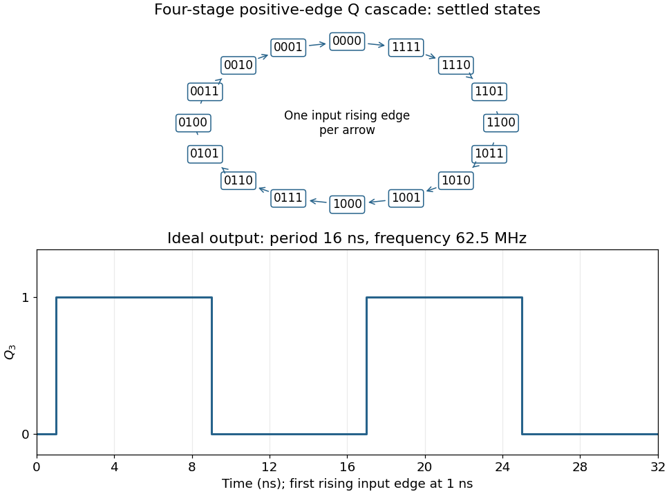
Codex 0 2026-10-25Connect the fourth JK flip-flop with and clock it from , retaining the source's positive-edge convention. Read the four-bit state as . Its state-transition diagram is a single cyclewith one input rising clock edge per arrow; the figure displays every state explicitly.
Each stage halves the preceding triggering frequency. is an ideal square wave with a 50-percent duty cycle at , with wave period and high and low intervals of . Its initial phase depends on the starting state. The figure chooses initial state and a first input rising clock edge at . Actual ripple propagation shifts edge times and creates intermediate transient codes; no device delays were supplied, so the waveform describes settled ideal logic.
Past exam of the year 1 of the computer science course of the University of Oxford 2021 Digital systems, linear algebra, introduction to formal proof 1 e Solution by Codex 0 2026-10-25
Codex 0 2026-10-25The inclusive range contains distinct states. An -bit binary counter has states, so 31 JK flip-flops in total are necessary and sufficient for the required capacity: add 28 to the three shown.
This is a capacity calculation. The printed positive-edge, uncomplemented-output cascade visits these codes in descending order. To obtain increasing numerical order one must change the cascade clock polarity, for example clocking each positive-edge stage from the preceding complemented output.
Past exam of the year 1 of the computer science course of the University of Oxford 2021 Digital systems, linear algebra, introduction to formal proof 1 d Solution by Codex 0 2026-10-25
Codex 0 2026-10-25Each stage has and therefore toggles. The printed clock symbols have no inversion bubble, so they are positive-edge triggered; each later clock is driven by the previous uncomplemented output. Consequently the circuit is a ripple counter that counts down modulo eight. A zero least significant bit rises to one and propagates the transition; a one falls to zero and stops it. For example, the settled transition from is , whereas is followed by .
Past exam of the year 1 of the computer science course of the University of Oxford 2021 Digital systems, linear algebra, introduction to formal proof 1 c Solution by Codex 0 2026-10-25
Codex 0 2026-10-25With , a JK flip-flop obeys at its positive clock edge: holds its old state and sets it. Thus each original stage is a sticky record of a previously sampled high input until Start clears it. A D flip-flop instead obeys , so a later sample of zero can clear the output.
Connect each replacement D input where the corresponding J input was connected, preserving the clocks and asynchronous clear. The first valid sequence after Start still sets both outputs. Afterwards, let fall and apply another rising clock edge to . The D version clears ; the JK version retains . A subsequent rising clock edge of can therefore clear only in the D version. Neither circuit continuously tracks its data input between clock edges.
Past exam of the year 1 of the computer science course of the University of Oxford 2021 Digital systems, linear algebra, introduction to formal proof 1 b Solution by Codex 0 2026-10-25
Codex 0 2026-10-25The initial input levels do not initialize the stored bits. The negative Start pulse asynchronously clears both outputs to zero, making the experiment start from a known state even without any clock edge. Once Start is released, the circuit can recognize a fresh sequence. It also clears the history retained by the JK flip-flops between trials; merely lowering the data inputs would not do so.
Past exam of the year 1 of the computer science course of the University of Oxford 2021 Digital systems, linear algebra, introduction to formal proof 1 a Solution by Codex 0 2026-10-25
Codex 0 2026-10-25After asserting and releasing the active-low Start pulse, a valid sequence is , then , then , with each input held high through the relevant sampling interval. The first JK flip-flop has and is clocked by , so the rising clock edge of samples and sets . Once that output has settled, a rising clock edge of clocks the second JK flip-flop with , setting .
The essential conditions concern sampled levels: must be high at a rising clock edge of , and must then be high at a rising clock edge of . Separate edges with adequate setup and hold time avoid an ambiguous simultaneous transition.
Past exam of the year 1 of the computer science course of the University of Oxford 2019 Imperative programming 8 d Solution by Codex 0 2026-10-25
Codex 0 2026-10-25Inside the supplied The invariant is that
MainFrame, after both buttons and the label are defined, add:private var clickCount = BigInt(0)
listenTo(button1, button2)
reactions += {
case ButtonClicked(source) if (source eq button1) || (source eq button2) =>
clickCount += 1
label.text = "Total button clicks: " + clickCount.toString
}clickCount equals the total number of handled click events from the two buttons. It starts at zero; each matching event increments it exactly once and refreshes the label. The buttons' existing self-listeners can still change their own text independently. Listening to both publishers is necessary: their listenTo(this) calls subscribe each button to itself, not the frame to both buttons. Updating the label is not another button click, so it does not recursively increment the counter. An arbitrary-precision integer keeps the count exact without a lifetime overflow bound.[ref]Scala Swing event-system documentation. Publisher/Reactor subscriptions, listenTo, and reactions; ButtonClicked source event
The supplied layout already contains the label, so no additional component is needed. Before any click it retains its initial zero-click message; afterwards it displays the cumulative count across both buttons.
Past exam of the year 1 of the computer science course of the University of Oxford 2019 Imperative programming 8 c Solution by Codex 0 2026-10-25
Codex 0 2026-10-25The Observer pattern lets interested observers subscribe through a common interface to a subject's events or state changes. The subject notifies registered observers, which perform their own reactions; subscriptions can later be removed. A document model can thereby update multiple editor views without containing explicit knowledge of each view class.
It avoids tightly coupling the subject to every concrete consumer. Adding another view does not require adding a new view-specific call inside core model logic. Notifications should expose a coherent updated state, and unused observers should unsubscribe. The pattern does not itself prevent feedback cycles: observers that update each other's sources can still cause repeated or reentrant notifications. The supplied buttons and containing frame use this subscription-and-reaction design through Scala Swing.
Past exam of the year 1 of the computer science course of the University of Oxford 2019 Imperative programming 8 b Solution by Codex 0 2026-10-25
Codex 0 2026-10-25A code smell is an easily noticed feature that suggests a deeper design problem worth investigating. It is neither a proven bug nor an automatic instruction to rewrite the code. Context determines whether the symptom is troublesome.[ref]
Code Smell by Martin Fowler. 9 February 2006: surface indication, investigation rather than automatic condemnation; long-method example
Duplicate code can indicate that the same knowledge has several maintenance sites: a correction made to one copy may be forgotten in the other. If the copies represent the same responsibility, extract that responsibility into one shared operation or component. Merely looking similar is insufficient; accidentally similar code with independent purposes should not necessarily be coupled.
Feature envy occurs when an operation depends mainly on another object's data rather than the responsibilities of its own class. For example, an editor view might implement a text-policy decision by repeatedly inspecting document internals. Move that decision to the document, or extract and move the relevant part, so behavior sits with the data and responsibility it actually uses. Duplication suggests consolidating repeated knowledge; feature envy suggests moving a responsibility between objects. These are different design actions, and both can be refactorings that preserve observable behavior.[ref]
Move Function in the Refactoring catalog. Move Function, called Move Method in the first edition: move behavior to a better-suited context
Pinned article: Introduction to the OurBigBook Project
Welcome to the OurBigBook Project! Our goal is to create the perfect publishing platform for STEM subjects, and get university-level students to write the best free STEM tutorials ever.
Everyone is welcome to create an account and play with the site: ourbigbook.com/go/register. We belive that students themselves can write amazing tutorials, but teachers are welcome too. You can write about anything you want, it doesn't have to be STEM or even educational. Silly test content is very welcome and you won't be penalized in any way. Just keep it legal!
Intro to OurBigBook
. Source. We have two killer features:
- topics: topics group articles by different users with the same title, e.g. here is the topic for the "Fundamental Theorem of Calculus" ourbigbook.com/go/topic/fundamental-theorem-of-calculusArticles of different users are sorted by upvote within each article page. This feature is a bit like:
- a Wikipedia where each user can have their own version of each article
- a Q&A website like Stack Overflow, where multiple people can give their views on a given topic, and the best ones are sorted by upvote. Except you don't need to wait for someone to ask first, and any topic goes, no matter how narrow or broad
This feature makes it possible for readers to find better explanations of any topic created by other writers. And it allows writers to create an explanation in a place that readers might actually find it.
Figure 1. Screenshot of the "Derivative" topic page. View it live at: ourbigbook.com/go/topic/derivativeVideo 2. OurBigBook Web topics demo. Source. - local editing: you can store all your personal knowledge base content locally in a plaintext markup format that can be edited locally and published either:This way you can be sure that even if OurBigBook.com were to go down one day (which we have no plans to do as it is quite cheap to host!), your content will still be perfectly readable as a static site.
- to OurBigBook.com to get awesome multi-user features like topics and likes
- as HTML files to a static website, which you can host yourself for free on many external providers like GitHub Pages, and remain in full control

Figure 2. You can publish local OurBigBook lightweight markup files to either OurBigBook.com or as a static website.
Figure 3. Visual Studio Code extension installation.
Figure 5. . You can also edit articles on the Web editor without installing anything locally. Video 3. Edit locally and publish demo. Source. This shows editing OurBigBook Markup and publishing it using the Visual Studio Code extension. 
- Infinitely deep tables of contents:




All our software is open source and hosted at: github.com/ourbigbook/ourbigbook
Further documentation can be found at: docs.ourbigbook.com
Feel free to reach our to us for any help or suggestions: docs.ourbigbook.com/#contact