
Past exam of the optics and electrodynamics course of the University of Cambridge 2017 4 Solution 2026-10-18
Gauge freedom. The magnetic vector potential satisfies . The transformationleaves unchanged because the curl of a gradient is zero. For time-dependent fields, transform the electric scalar potential as as well, so that is unchanged. The scalar must have the regularity and single-valuedness appropriate to the physical region and its boundary conditions. Local values of therefore depend on the gauge transformation.
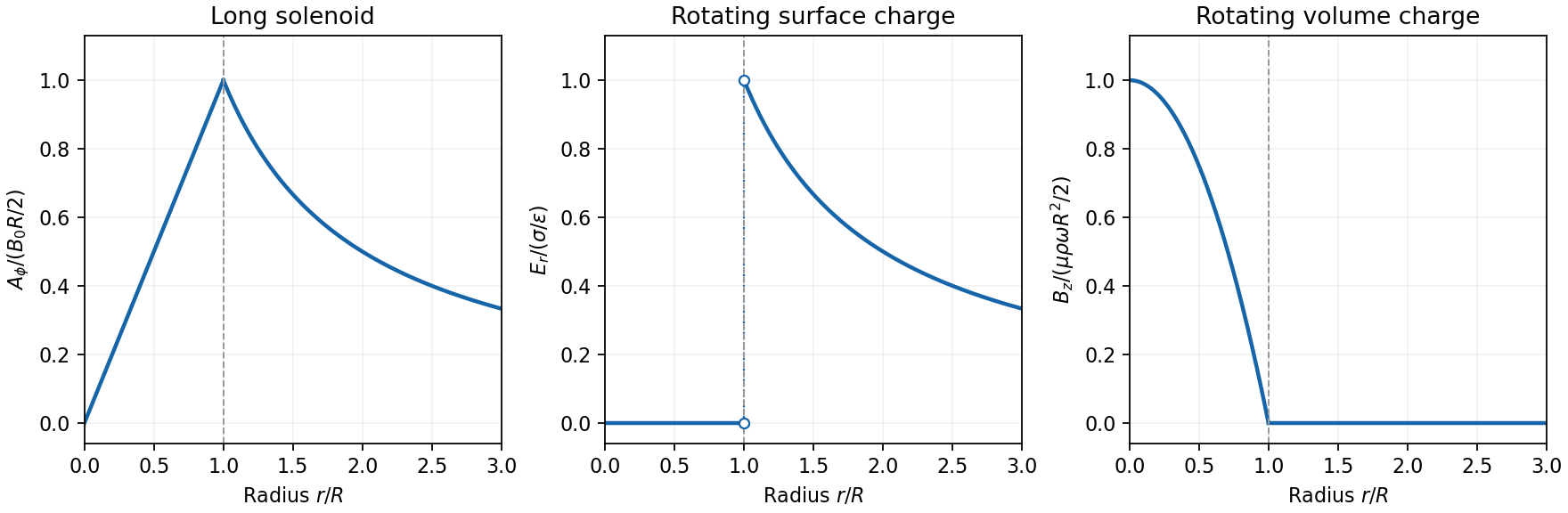
Gauge and nonzero component. In the standard axisymmetric Coulomb gauge representative for the long-solenoid approximation,The divergence vanishes since is independent of the azimuth. Inside, this agrees with the usual symmetric gauge representative . The Coulomb gauge condition alone does not force the other two components to vanish; the symmetry, regularity and customary boundary choice select this representative from the remaining gauge freedom.
Radial dependence. Write the interior magnetic field as , where for a vacuum solenoid of solenoid turn density . Its exterior magnetic field vanishes in the infinitely long idealization. Applying Stokes theorem to a coaxial circle gives . Therefore the Coulomb-gauge vector potential of a long solenoid isIt grows linearly inside, is continuous at , and decays as outside. Although its exterior curl is zero, its circulation is the enclosed magnetic flux . No regular single-valued gauge function removes it throughout the exterior while preserving this circulation.
Electric field of the rotating charged surface. For clarity retain absolute permittivity and permeability in the cylinder formulae; setting them to unity gives the rationalized-unit convention in the question. If the stated unity means relative material constants in SI, use instead. Assume prescribed charge densities in the laboratory frame and the nonrelativistic, steady-rotation model.
The axisymmetric surface charge is stationary as a distribution even while the material rotates. A Gaussian cylinder of length has enclosed charge zero for and for . Gauss's law therefore givesThe radial electric field jumps from zero to at the surface and then decays as . Its direction reverses for negative . The angular velocity does not enter this electric-field result for a specified surface charge.
Magnetic field of the volume-charged cylinder. A shell of radius and thickness has surface charge , azimuthal surface current , and the field of an infinite solenoid: inside that shell and zero outside it. At radius , only shells with contribute. Thus the magnetic field of a rotating charged solid cylinder isWith no applied background magnetic field, outside. The profile is parabolic, largest on the axis and zero at the boundary. The sign follows . As a check, the current density is , and Ampère's circuital law gives , as required.

Electron impulse when the current is switched off. Choose positive so the initial magnetic flux is along . Faraday's law of induction gives, outside the solenoid,For an Electron of electric charge , treat its position as fixed while the short pulse acts. The inductive impulse outside a switched solenoid isConsequently the nonrelativistic final velocity isThe induced electric field circulates in the positive azimuthal direction while a positive flux decreases, so the Electron accelerates in the negative direction. Once the pulse has passed, there is no exterior field and it travels along the tangent at the impulse point, rather than continuing in a circular orbit. If the resulting momentum is relativistic, use instead. The sudden-switch result assumes negligible displacement during the pulse and the usual quasistatic electromagnetic induction approximation; “instantaneous” switching does not mean instantaneous propagation of fields to arbitrary distance.
One can check the sign using conserved canonical angular momentum: axial symmetry conserves . Initially , and finally , so .
Interferometric measurement at constant current. Use a coherent Electron beam split into two paths passing on opposite sides of a shielded long solenoid, then recombine them to form interference fringes. Keep the current constant during the passage and suppress leakage fields on the paths. In the Aharonov-Bohm effect, the phase difference due to the magnetic vector potential is the closed-loop integralThe overall sign reverses if the path orientation is reversed. The displacement in fringe periods is , so the measured fringe shift is linear in and repeats whenA gauge transformation adds a gradient whose closed-loop integral vanishes for a single-valued . Endpoint changes in Electron wavefunction phase cancel in the interference measurement. The measured Aharonov-Bohm phase is therefore gauge invariant: it determines the flux, or equivalently the circulation of . In the chosen Coulomb gauge this implies , but the experiment does not select or measure a unique local vector potential independently of gauge.
Far field of the rotating sphere. Interpret uniform charge as uniform volume charge of total , and take . The magnetic dipole moment of a rigidly rotating charge distribution isIts axial component is . For a solid sphere, and , soThe magnetic field of a rotating charged spherical body is a static magnetic dipole field at large distances:In particular, . Both the angular mean of the magnitude and its root mean square therefore scale as ; the latter is . The angular average of the vector is zero, which is different from average strength. Steady rotation leaves the charge and current distributions stationary, so this is magnetostatics, not a radiative field. If uniform charge instead means a thin spherical surface, replace the dipole moment by ; the angular pattern and scaling are unchanged.
Past exam of the optics and electrodynamics course of the University of Cambridge 2017 3 Solution 2026-10-18
General pure state. Use time dependence . The most general nonzero Jones vector can be writtenThere are four real parameters in the full complex field. Removing overall intensity and the unobservable common phase leaves two real degrees of freedom for pure polarization, and . Their endpoint degeneracies simply reflect the fact that the phase of a vanishing component is irrelevant. A single Jones vector cannot represent partially polarized light.
Three linear polarizers. Define the transmission axis . An ideal linear polarizer has Jones matrix . For definiteness label as right-circular in the chosen convention; reversing the handedness convention changes no intensity below. The first polarizer produces . The intermediate polarizer and final analyzer then giveso Malus's law givesThe maximum is at , and the transmission vanishes at . The first polarizer accounts for an initial factor ; retaining that factor is essential when quoting transmission relative to the incident circularly polarized beam.
Waveplate and quarter-wave matrix. A lossless waveplate has linear birefringence: its orthogonal fast and slow axes have indices . A thickness produces slow-minus-fast phase retardationResolving the incident Jones vector into the plate axes, advancing the two phases and transforming back gives, up to a common phase,A quarter-wave plate has modulo . With and , its Jones matrix is thereforeIn particular . Equal incident components along the two axes acquire a relative quarter-cycle phase, converting linear polarization to circular polarization; an incident component along either principal axis stays linearly polarized.
Half-wave replacement. A half-wave plate has and henceIt converts the -polarized output of the first polarizer to a linear state at angle . The final analyzer givesThe maximum is , because the ideal half-wave plate loses no light after the first polarizer.
Quarter-wave replacement. The transmitted amplitude is , givingMore generally, the retarder gives . All three requested curves have the same zeros and angular period, but different heights:
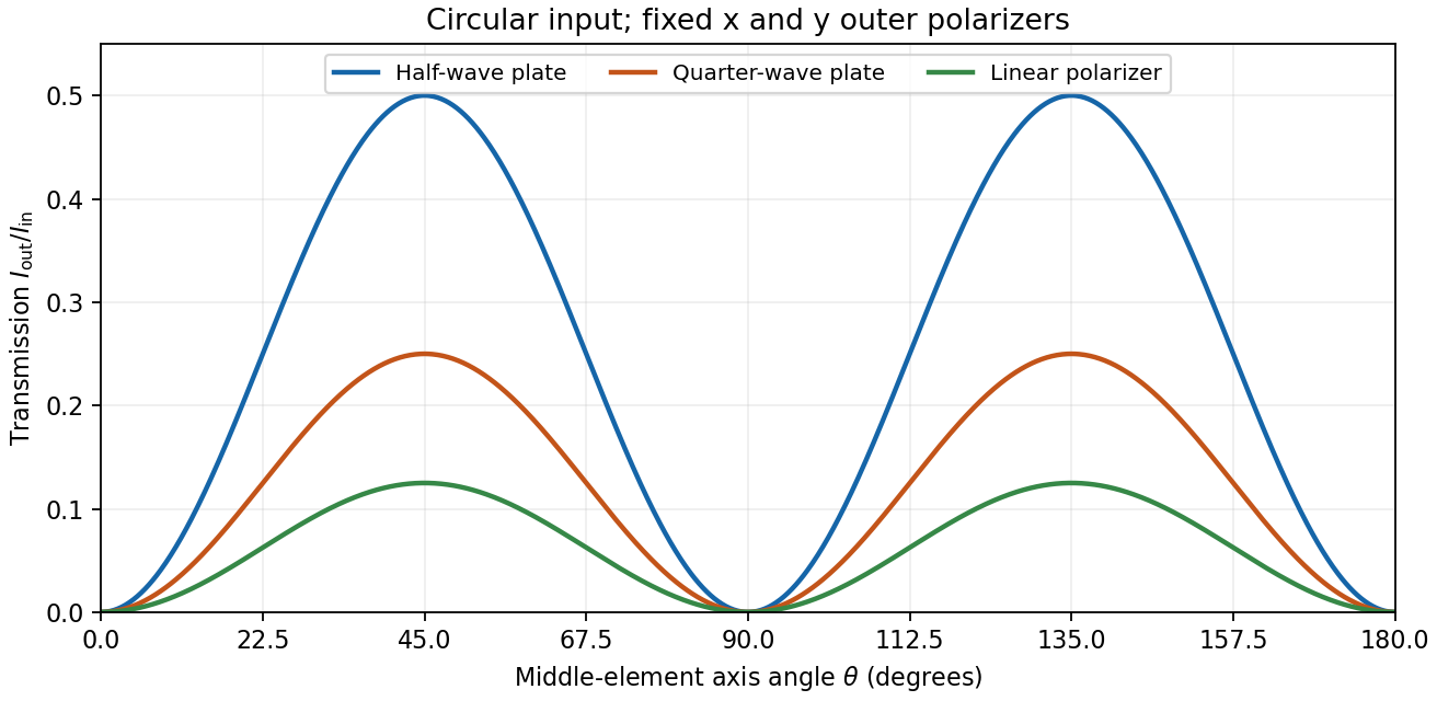
Transmission through crossed outer polarizers with three different middle elements
. Details. 
Preparing an arbitrary ellipse. Yes: two rotatable quarter-wave plates already suffice. Let the input left-circular state be . Up to an overall phase, any target pure polarization can be parameterized by its polarization ellipse:Here is the major-axis orientation, and sets the signed minor-to-major semiaxis ratio . First note directly from thatChoose the two fast-axis angles asThe first quarter-wave plate produces linear light at . In the axes of the second, its components are ; the second gives precisely . This proves pure-polarization preparation with two quarter-wave plates, including the linear and circular limiting cases. A half-wave plate can also rotate the axes, but is not required. The phrase about left-handed input is understood as left-circular light in this construction; the explicit vector fixes the convention.
Switchable retardation. The electro-optic Kerr effect induces linear birefringence quadratic in a static transverse electric field. Defining the coefficient by , its phase retardation isThe two eigenpolarizations are linear, parallel and perpendicular to the applied field. Thus an appropriate field produces a switchable quarter-wave plate:The sign of determines which axis is fast. Switching the field off removes the induced retardation, assuming no residual birefringence.
The Faraday effect instead gives circular birefringence for a longitudinal magnetic field. The two circular eigenmodes acquire different phases, rotating a linear polarization throughwith sign set by the handedness convention and the Verdet constant . Its Jones matrix in the linear basis is a real rotation, up to a common phase. It preserves the ellipticity of a pure state, so a linear input remains linear. A phase difference between circular eigenmodes rotates a linear state by ; it does not make it circular. The Kerr device supplies the switchable quarter-wave plate; a Faraday rotator alone does not.
There are unlisted articles, also show them or only show them.