Consider two identical, lossless parallel mirrors with intensity reflectivity , separation , and a uniform transparent medium of refractive index . Fix one polarization of an electromagnetic wave and an internal angle of incidence measured from the mirror normal vector. Illuminate with a monochromatic wave having planar wavefronts; the emerging contributions must overlap coherently in the detected direction. Define using the same incident and exit media. Each mirror transmits a fraction of incident power. Its reflected wave amplitude has magnitude , so two internal specular reflections multiply the circulating complex amplitude by magnitude , not .
Let be the vacuum wavelength and choose the reflection wave phase convention in which the product of the two internal amplitude reflection coefficients is real and positive. The phase difference between successive transmitted contributions, evaluated on a common outgoing wavefront, isWith other mirror coatings or phase conventions, use the total , where is the sum of the two internal reflection wave phases. The stated resonance positions presume modulo ; a constant nonzero shifts them, while a frequency-dependent one can also change their spacing.
Why does the cosine appear rather than its reciprocal? Inside the gap, the extra two legs have optical path length . But the later emerging contribution starts farther along the mirror. Comparing both on one outgoing wavefront subtracts from that path difference, leaving . Equivalently, a plane wave's mirror-normal wavevector component is , so the round-trip wave phase is . The diagram uses the same medium outside and inside to show the common-wavefront subtraction directly; at a refracting exit interface, tangential wavevector matching in Snell's law supplies the same result.
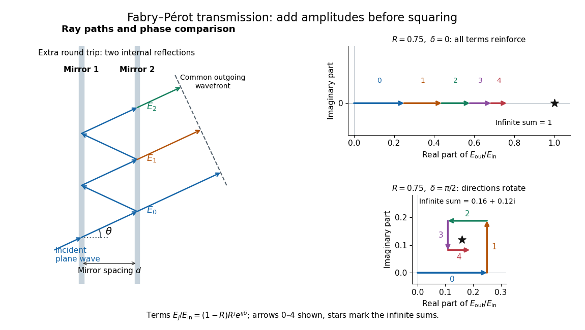

Absorb the common first-pass wave phase into the incident complex amplitude . Successive transmitted contributions are , , and so on. The superposition principle and the convergent geometric series giveThe last step expands the squared complex modulus as . This transmission profile is often called the Airy transmission function; it is distinct from the Airy disk, a diffraction image of a circular aperture. The University of Washington's lab handout gives the same transmission profile and distinguishes mirror reflectivity from other sources of peak broadening.[ref]
Fabry-Perot Interferometer, University of Washington Physics 331. Fabry-Perot Interferometer, theory equation (2), Finesse discussion, equations (4)–(8)
For an original example, set . At , the amplitudes add to , so . At , they alternate in sign and add to , so . At , the amplitude is and . Adding the individual intensities instead would give , independent of wave phase; that discards the wave interference responsible for the peaks.
In general the maximum is at , with integer , and the minimum is halfway between peaks. Perfect resonant transmission requires identical lossless mirrors, coherent illumination, and sufficient time to establish the steady field. Absorption, unequal mirror transmission, finite beams that fail to overlap, and fluctuations of can reduce it. The exactly reflecting case is excluded: no incident power enters through a perfectly reflecting mirror, and the resonant limit is singular.
Articles by others on the same topic
There are currently no matching articles.