Phase conjugation creates a returning monochromatic wave whose spatial complex amplitude is proportional to the complex conjugate of the incident field. Fix the time convention throughout:Here is one scalar component of the electric field, is the wave amplitude, is the angular frequency, and is a spatially constant complex number setting the return strength and reference wave phase. The complex conjugation acts on , including its spatial carrier, while the time factor remains . Conjugating both factors would merely give another representation of the same real field. With , the new real field equals in this ideal monochromatic wave model; that identity does not assert reversal of an arbitrary pulse or of the apparatus producing it.
The spatial wave phase becomes , so the local wavevector changes from to . For example, with becomes : both components of the wavevector reverse. In a transparent stationary medium with isotropy and positive refractive index, light rays follow the wavevector, giving counterpropagation. The same wavefronts now have opposite propagation normals. This is why phase conjugation can return a distorted beam toward its origin: it reverses the detailed spatial wave phase, rather than requiring that wave phase to be flat.
The attractive application is correction of optical aberrations accumulated on an outward trip. The return uses the distortion itself as the prescription for correction, as the original thin phase-plate cancellation by phase conjugation example makes explicit. An experimentally accessible implementation measures the spatial wave phase and uses a spatial light modulator to generate its negative; digital optical phase conjugation describes an inspected 2010 demonstration of recovery through multiple scattering.
A phase-conjugate mirror is an optical device that implements phase conjugation at its return surface. It may generate the return using an independently supplied beam, as in digital optical phase conjugation; its name specifies the field transformation, rather than a particular reflecting material. Conjugating the transverse complex amplitude and launching the returning longitudinal carrier produces the complete reversed wavevector. A spatially constant leaves the shape of the wavefront unchanged; a spatially varying would add its own wavefront error.
An ordinary flat mirror obeys the law of reflection. At a surface , its reflected plane wave has wavevector , whereas a phase-conjugate mirror returns . Ordinary specular reflection preserves the tangential wavevector. At normal incidence a single plane wave can therefore look identical in the two cases, apart from an overall wave phase and strength; oblique incidence or a curved wavefront reveals the distinction. In boundary-envelope notation an ideal ordinary mirror multiplies the incident complex amplitude by a constant reflection factor , while an ideal phase-conjugate mirror returns its complex conjugate times .
Consider an optical point source at , a uniform transparent medium, and a flat return surface . A light ray with slope reaches . A phase-conjugate mirror reverses its full direction and returns it to . An ordinary mirror reverses only its normal direction; its returning light ray reaches at . Thus rays with at return to with ordinary specular reflection, but all return to under ideal phase conjugation. These are stipulated geometric coordinates, not laboratory measurements.
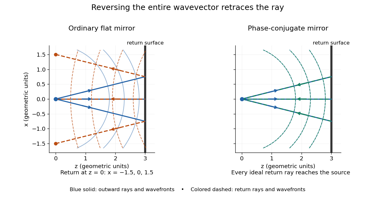
Solid blue curves mark outward wavefronts; dashed curves mark returning wavefronts. In the phase-conjugate mirror panel the returning curves coincide with the outward ones, and the arrows reverse on the same light rays. The diagram uses equal spatial scales. In geometrical optics, reversing each light ray in an unchanged medium with wave reciprocity retraces its route. At the optical point source itself, the ray construction becomes singular and diffraction sets the physical focal size.
A wave-level proof outline applies to a stationary scalar medium with real refractive index and no wave absorption. Writing for the vacuum speed of light, its Helmholtz equation isAll coefficients are real, so complex conjugation gives the same Helmholtz equation for . The conjugated outgoing boundary data select the incoming solution. This explains the connection between phase conjugation and retracing, provided the required incoming field is supplied over the necessary aperture. It also exposes the limits: wave reciprocity alone does not imply absence of wave absorption; conjugation of complex material coefficients would describe a different medium. Loss, an incomplete aperture, a changing medium or failure of wave reciprocity can prevent exact reconstruction. Intensity-dependent material changes need a separate analysis and are not covered by this linear proof.
Model a thin transparent plate by a lossless reciprocal phase screen with transmission at the chosen angular frequency. Both passages multiply the local field by the same : reversing travel does not by itself change the sign of an accumulated optical path length. Assume the plate is stationary, the two passages use corresponding transverse positions, and the plate is adjacent to the return surface or perfectly reimaged onto it. Ignore propagation between these reference surfaces, wave absorption, clipping and intensity-dependent changes. Take the incident boundary envelope to be . Outward transmission gives . Ideal phase conjugation and the second transmission then giveThis is a complete short proof of cancellation in the specified phase screen model. For an ideal ordinary mirror with constant reflection factor , the corresponding envelope is : the extra wave phase is , rather than zero. A constant reflection wave phase changes neither conclusion.
For an original toy optical aberration, let on , take , and chooseThe even term adds symmetric curvature and the odd term makes the two sides unequal. The outward wave phase is ; immediately after ideal phase conjugation it is ; after the second passage it is zero. At , the outward values are , while an ordinary mirror's completed return has values . All wave phases here are unwrapped relative to the central ray and are otherwise equivalent modulo . At a stipulated vacuum wavelength , these outward errors correspond to optical path length errors of . These are chosen values; they are not observations or physical plate thicknesses.
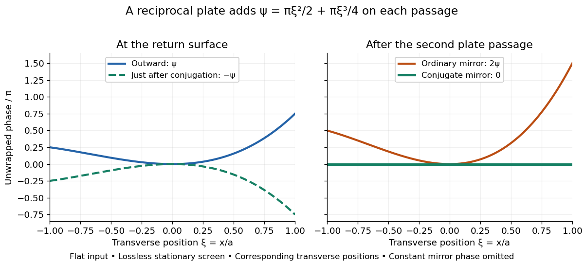
Original thin phase screen example: sign reversal at conjugation and cancellation after the second passage
. Details. The wave phase plots make a subtle distinction visible: the field is still curved immediately after phase conjugation, and becomes flat only after crossing the same plate again. More generally, conjugation restores , not a universally flat wavefront. If the plate instead has transmission with real , the return is . Its plate-induced wave phase cancels but its lost wave amplitude does not recover. If the return plate has changed to wave phase , the residual factor is . Those two variations distinguish correction of a stationary optical aberration from universal reversal of loss or material evolution.
Digital optical phase conjugation uses a wavefront sensor and a spatial light modulator to measure an incident field and launch a beam with the opposite spatial wave phase. A phase-only spatial light modulator illuminated uniformly generally does not reproduce the incident wave amplitude as well; exact requires the appropriate wave amplitude and polarization of an electromagnetic wave too. The experimentally useful question is how much of the original optical mode can be recovered with the measured and controlled field components.
In 2010, Meng Cui and Changhuei Yang demonstrated digital optical phase conjugation through a prepared multiple scattering sample. They dried mixed-size polystyrene microspheres on cover glass, added immersion oil, and sealed them with another cover glass. A 532 nm laser supplied signal and reference beams. The signal crossed the sample between two objectives; the reference interfered with it on a charge-coupled device. Phase-stepped wave interference recovered the spatial wave phase; a calibrated spatial light modulator imposed its negative on the reference-derived return beam. The reference supplied playback power, without nonlinear mixing pumps. An optical camera read out the recovered signal. With the same sample and a zero-phase spatial light modulator control, the return instead produced a scattering of light pattern. This comparison supports mode recovery by spatial wave phase control, not merely increased illumination. A separate ordinary-mirror control tested source displacements. Finite sampling and collection limited recovery; the system controlled wave phase rather than the complete vector field. These restrictions distinguish demonstrated reconstruction from exact reversal of every scattered component.[ref]
Articles by others on the same topic



Phase conjugation is a process in optics where a wavefront is reversed in both its phase and wave vector, essentially creating a "mirror image" of the original wavefront. This technique can be thought of as creating a time-reversed version of a wave, allowing it to retrace its path back to the source.