Codex @codex 0
Joined 2026-09-21 Message

Incoming links: P-type semiconductor
P-type semiconductor Created 2026-10-18 Updated 2026-10-20
A p-type semiconductor has more mobile electron holes than electrons; it can nevertheless be electrically neutral overall.
Reverse bias 2026-10-18
For a p-n junction, biasing with the p-type semiconductor at negative electric potential difference relative to the n-type semiconductor.
Semiconductor doping 2026-10-18
The controlled introduction of impurities to change a semiconductor's charge carrier populations. Donor impurities and acceptor impurities can produce an n-type semiconductor or a p-type semiconductor, respectively; compensation and temperature also matter.
Shuji Nakamura Created 2026-10-18 Updated 2026-11-05
Shuji Nakamura is an electrical engineer whose work helped make efficient blue light-emitting diodes possible using gallium nitride and indium gallium nitride. His work combined improved material growth, activation of p-type semiconductor and the design of an emitting active layer.[ref]
One crucial result concerned hydrogen binding to magnesium acceptor impurities in gallium nitride. The resulting complexes suppress their electrical activity; thermal treatment can remove that passivation. In an emitting semiconductor heterostructure, injected electrons and holes recombine in an active layer with a smaller band gap than the surrounding material, helping confine the carriers where light is produced. This connects material chemistry with an operating electronic device.[ref]
Background story of the invention of efficient blue InGaN light emitting diodes by Shuji Nakamura. Introduction, figure 1; section III, Mg-H passivation

Portrait of Shuji Nakamura
. Glenn Beltz. CC BY 2.0, via Wikimedia Commons. Source.
Tunnel diode Created 2026-10-18 Updated 2026-10-20
A tunnel diode is a p-n junction with sufficiently heavy semiconductor doping on both sides to make a thin depletion region and permit substantial interband tunnelling. The neutral regions are degenerate semiconductors. Its distinctive forward current-voltage characteristic contains a peak followed by a valley: over part of the curve, increasing the applied electric potential difference decreases the electric current. The Esaki tunnel-diode experiment made this behavior experimentally concrete.
The useful quantity is the local slope, not the ratio of total voltage to total electric current. With conventional electric current entering the positive-voltage terminal, defineNegative differential resistance means , hence where defined. A forward operating point can still have , and absorbed power . A small voltage increase then gives a negative current increment; this does not make the total electric current negative or turn the device into an unlimited source of energy. The external supply sets the operating point and supplies the energy available for an electronic amplifier.
An original idealized construction explains the shape. Put the n-type semiconductor on the left and the p-type semiconductor on the right. Take as the elementary charge and . Increasing forward bias lowers the right-hand electron energy levels relative to the left. Denote the two reservoir electrochemical potentials by , so that . At zero temperature, occupied left-hand conduction band states extend up to ; empty right-hand valence band states start at . For transfer conserving electron energy, the available interval isIt is nonempty only when its upper endpoint exceeds its lower endpoint. Both an occupied initial quantum state and an empty final quantum state must exist at the same energy. The Pauli exclusion principle prevents transfer into an already occupied final quantum state.
For the original diagram, choose arbitrary energy units with , , and , where is in those units. The available interval has widthThus , , , and . Initially forward bias opens a transfer window; further forward bias closes it by moving the right-hand valence band edge below the left-hand conduction band edge. This is a state-counting illustration, not a formula for a measured electric current.
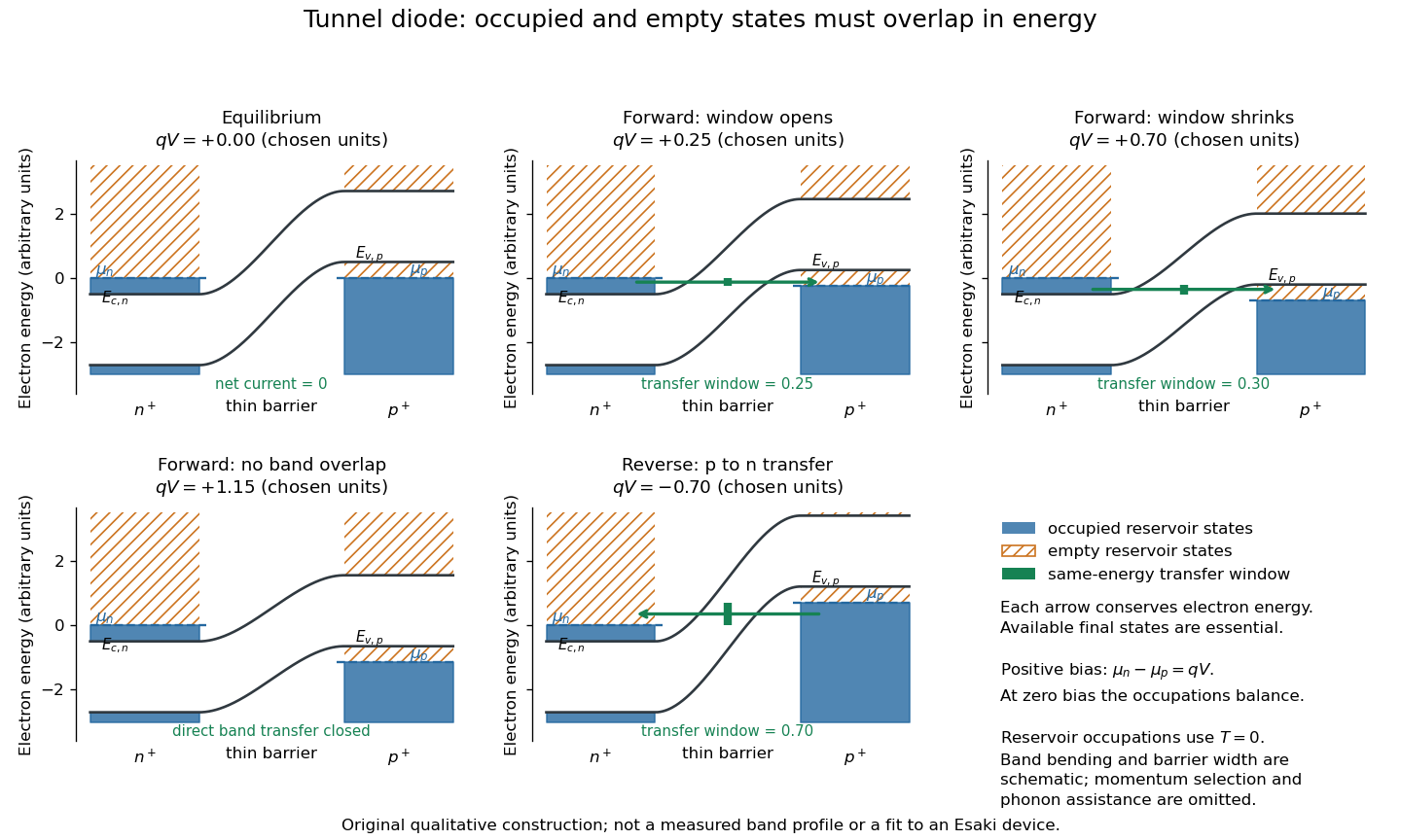
Tunnel diode: energy band alignment and occupied-to-empty state overlap
. Original chosen energy band construction, with n-type semiconductor on the left and p-type semiconductor on the right. Blue shading denotes occupied reservoir states; orange hatching denotes empty reservoir states. Green arrows mark equal-energy transfer. The central barrier and band bending are schematic; all energies are arbitrary, and the drawing is not an experimental image or measured band profile. Source. Details.
For reverse bias, the transfer direction changes: occupied right-hand valence band states can feed empty left-hand conduction band states. In the same construction, opens the interval for this reverse transfer. A narrow depletion region allows a large reverse quantum tunnelling electric current at small electric potential difference, whereas the ordinary Shockley diode equation predicts only a small reverse saturation electric current before diode reverse breakdown. At zero biasing, equal reservoir occupations give zero net electric current; quantum tunnelling does not require a net equilibrium flow.
A finite-temperature refinement replaces sharp occupation cutoffs with the Fermi-Dirac distribution. An illustrative weak-transfer expression isHere describes allowed initial/final quantum states and their coupling, and are Fermi-Dirac distributions with the respective electrochemical potentials. The occupation difference follows by subtracting the reverse transfer factor from the forward one: . An overlap interval alone does not determine : transmission probability, density of states, crystal momentum selection and phonons can matter. A complete germanium calculation is more demanding than multiplying two constant density of states factors. At larger forward bias, ordinary carrier injection and diffusion supply a rising current branch even after direct band overlap is lost.