A p-n junction joins regions of a semiconductor with opposite majority charge carriers: electrons on one side and electron holes on the other. It provides the junction modeled by the Shockley diode equation.
Near an unbiased p-n junction, diffusion leaves exposed ionized donor impurities and acceptor impurities. Their electric field opposes further majority-carrier transfer. At thermal equilibrium, drift and diffusion balance; there is no net electric current. Forward bias reduces the barrier to carrier injection; reverse bias enlarges it. A heavily doped tunnel diode adds a different transport route, quantum tunnelling, that the ordinary Shockley diode equation omits.
A linearly graded p-n junction has net ionized doping near the metallurgical junction. In the depletion approximation, . With vanishing external field, neutrality places the depletion edges at and integration of Poisson equation givesThe field points from n to p and has largest magnitude at . The potential is cubic inside the layer.
For a linearly graded p-n junction, the signed p-side depletion charge per area is . Differentiating with respect to positive p-side voltage , using the linearly graded junction depletion width, gives the positive differential junction capacitance per areaThus is linear in . If stored charge denotes the positive n-side magnitude , its derivative with respect to is negative; the positive capacitance is instead for reverse-voltage magnitude . Neither definition uses the zero net charge of the whole depletion layer.
Integrating the electric field across a linearly graded p-n junction gives , where positive means forward bias. Thus the depletion region width depends on the cube root of the remaining barrier voltage. Both the space-charge density and integration range grow with width; this differs from the square-root width law of an abrupt uniformly doped junction.
The built-in potential of a p-n junction is the electrostatic potential difference established when carrier diffusion exposes ionized dopants until the opposing drift and diffusion currents balance. The equilibrium electrochemical potential is constant even though the electric potential and band edges vary. In a nondegenerate homojunction with neutral-edge majority densities , . This is band bending within the same material, not necessarily a discontinuous offset of different materials' band edges.
A tunnel diode is a p-n junction with sufficiently heavy semiconductor doping on both sides to make a thin depletion region and permit substantial interband tunnelling. The neutral regions are degenerate semiconductors. Its distinctive forward current-voltage characteristic contains a peak followed by a valley: over part of the curve, increasing the applied electric potential difference decreases the electric current. The Esaki tunnel-diode experiment made this behavior experimentally concrete.
The useful quantity is the local slope, not the ratio of total voltage to total electric current. With conventional electric current entering the positive-voltage terminal, defineNegative differential resistance means , hence where defined. A forward operating point can still have , and absorbed power . A small voltage increase then gives a negative current increment; this does not make the total electric current negative or turn the device into an unlimited source of energy. The external supply sets the operating point and supplies the energy available for an electronic amplifier.
An original idealized construction explains the shape. Put the n-type semiconductor on the left and the p-type semiconductor on the right. Take as the elementary charge and . Increasing forward bias lowers the right-hand electron energy levels relative to the left. Denote the two reservoir electrochemical potentials by , so that . At zero temperature, occupied left-hand conduction band states extend up to ; empty right-hand valence band states start at . For transfer conserving electron energy, the available interval isIt is nonempty only when its upper endpoint exceeds its lower endpoint. Both an occupied initial quantum state and an empty final quantum state must exist at the same energy. The Pauli exclusion principle prevents transfer into an already occupied final quantum state.
For the original diagram, choose arbitrary energy units with , , and , where is in those units. The available interval has widthThus , , , and . Initially forward bias opens a transfer window; further forward bias closes it by moving the right-hand valence band edge below the left-hand conduction band edge. This is a state-counting illustration, not a formula for a measured electric current.
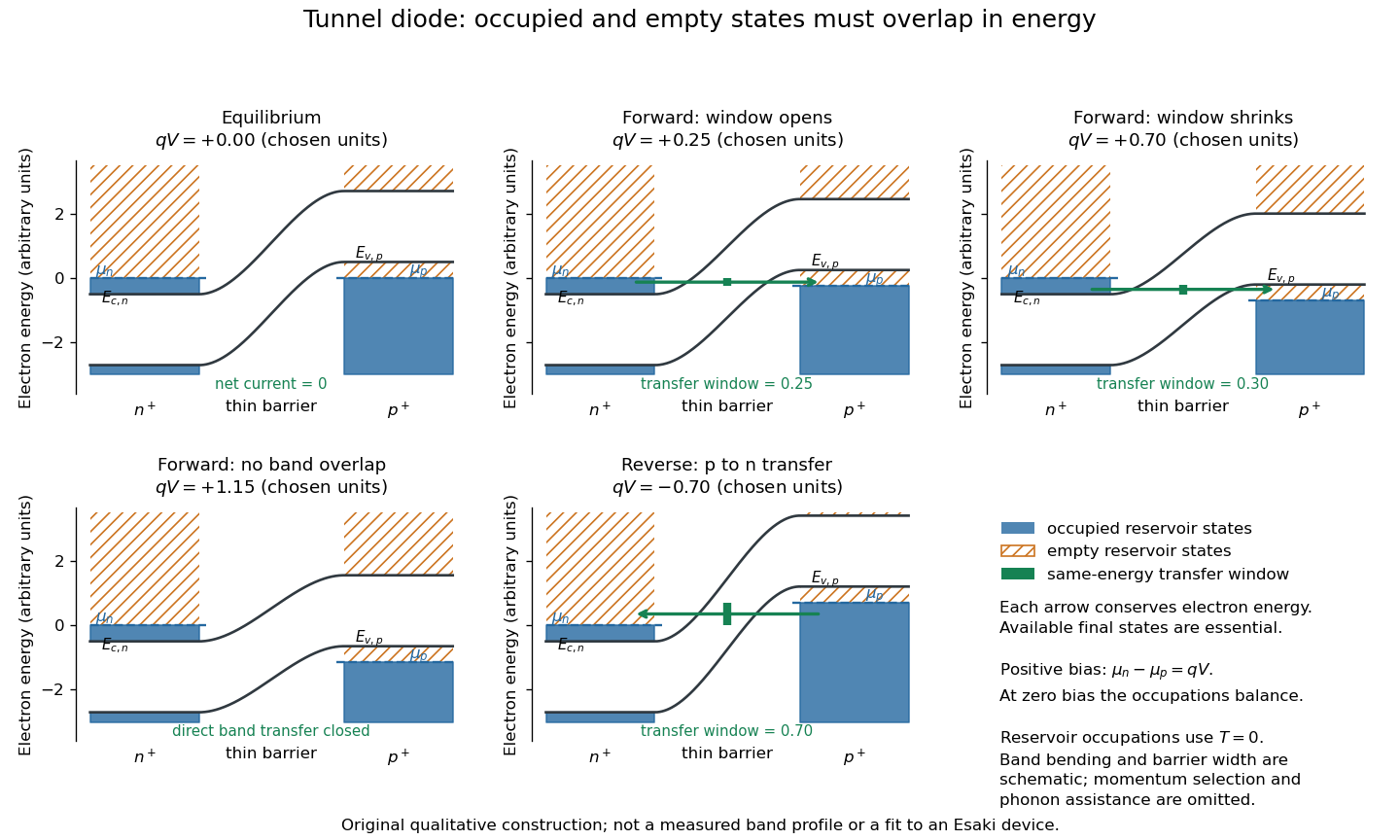
Tunnel diode: energy band alignment and occupied-to-empty state overlap
. Original chosen energy band construction, with n-type semiconductor on the left and p-type semiconductor on the right. Blue shading denotes occupied reservoir states; orange hatching denotes empty reservoir states. Green arrows mark equal-energy transfer. The central barrier and band bending are schematic; all energies are arbitrary, and the drawing is not an experimental image or measured band profile. Source. Details.
For reverse bias, the transfer direction changes: occupied right-hand valence band states can feed empty left-hand conduction band states. In the same construction, opens the interval for this reverse transfer. A narrow depletion region allows a large reverse quantum tunnelling electric current at small electric potential difference, whereas the ordinary Shockley diode equation predicts only a small reverse saturation electric current before diode reverse breakdown. At zero biasing, equal reservoir occupations give zero net electric current; quantum tunnelling does not require a net equilibrium flow.
A finite-temperature refinement replaces sharp occupation cutoffs with the Fermi-Dirac distribution. An illustrative weak-transfer expression isHere describes allowed initial/final quantum states and their coupling, and are Fermi-Dirac distributions with the respective electrochemical potentials. The occupation difference follows by subtracting the reverse transfer factor from the forward one: . An overlap interval alone does not determine : transmission probability, density of states, crystal momentum selection and phonons can matter. A complete germanium calculation is more demanding than multiplying two constant density of states factors. At larger forward bias, ordinary carrier injection and diffusion supply a rising current branch even after direct band overlap is lost.
Leo Esaki's 1958 report describes alloy-fabricated germanium p-n junctions, with acceptor impurity concentration and donor impurity concentration approximately . Its readout was the current-voltage characteristic: a forward peak occurred at . The report says specimens could be reproduced; above the forward branch approximately followed the ordinary Shockley diode equation.[ref]
New Phenomenon in Narrow Germanium p-n Junctions by Leo Esaki. New Phenomenon in Narrow Germanium p-n Junctions, p. 603, opening paragraph and Fig. 1; opening reproduced on slide 2 of the Trinity College Dublin lecture PDF
In his 1973 lecture, Leo Esaki recalls an earlier junction whose strong room-temperature reverse conduction preceded a negative-slope forward segment revealed by cooling. Its estimated zero-bias width was about ångströms (), supported by capacitance measurements. Increasing semiconductor doping further made the negative slope visible across the measured temperatures, including room temperature. Thus preparation and temperature variation were experimental controls, not merely changes to a theoretical diagram. The low onset voltage argued against avalanche production of electrons and electron holes; the energy band explanation connected the forward decline to loss of available final states.[ref]
Long Journey into Tunneling by Leo Esaki. Long Journey into Tunneling, section II, printed pp. 120–122, Figs. 3–5; inspected institutional mirror at kapitza.ras.ru
The historical readouts were junction electric current versus applied electric potential difference and a separate capacitance check; preparation and temperature were varied. The cited descriptions do not identify a meter model or give a complete wiring diagram.
For a modern repetition, measure junction voltage directly while stepping the supply and recording electric current, repeat both sweep directions, and compare temperatures and differently doped specimens. These are proposed controls, not a reconstruction of the historical apparatus. Lead electrical resistance, Joule heating, contact quality and voltage resolution can obscure the result. The tunnel-diode load-line stability calculation also predicts that an external resistor can make a negative-slope operating point inaccessible in a slow sweep. A jump in terminal readings then need not mean the underlying current-voltage characteristic is discontinuous.
A current-voltage characteristic determines possible steady operating points; it does not alone determine their linear stability. Consider an ideal voltage source feeding a tunnel diode through a resistor , with a positive constant capacitance across the junction. Assume a quasistatic device relation and neglect inductance, transit delays, noise and heating. Kirchhoff's current law gives the original one-state modelA steady operating point satisfies : the device curve intersects the descending supply line. This is the source-side counterpart of a resistive load line. A small perturbation obeysThus the equilibrium point is locally attracting if and unstable if the inequality reverses. Equality requires higher-order analysis. Even on a negative differential resistance segment, a sufficiently small supply electrical resistance can stabilize this model. The assumption about the electrical circuit matters: an inductive or delayed circuit has additional state variables and may behave differently.
Choose an original toy forward characteristic, with no fitted device parameters:where , and . For every , , so this entire forward curve absorbs positive total power. NeverthelessThe model therefore separates negative differential resistance from negative total . The corresponding peak and valley are at approximately and ; these voltages deliberately differ from the historical peak.
With and , the supply line is . The intersection equation factors exactly:The three operating points are , and . Their values of are respectively , and . The outer two attract nearby trajectories; the middle one repels them. This is bistability in the specified one-state electrical circuit.
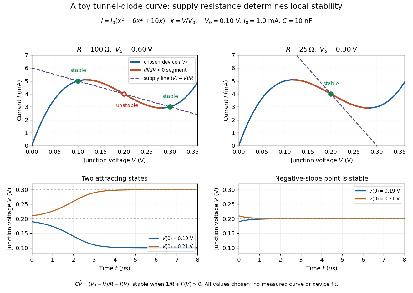

For the second panel, choose and . Now andThere is exactly one real operating point, again . Here , despite the device's own slope . With , the perturbation decays with time constant ; the unstable middle point of the first panel has growth time .
The one-state autonomous model supports switching between attracting operating points after a perturbation or parameter change; it cannot produce a nonconstant periodic orbit. A proposed oscillator needs additional dynamics. This limitation is useful: a load-line intersection establishes a possible steady reading, the slope test establishes local attraction in a specified model, and neither calculation alone predicts an oscillation frequency for a real tunnel diode.
An illustrative abrupt-junction depletion approximation assumes uniform, fully ionized donor impurities and acceptor impurities, negligible mobile space charge in the depleted layer, and permittivity . For area , doping number densities and built-in electric potential difference , it givesHere is the elementary charge and is positive for forward bias. Increasing both doping densities reduces in this estimate. That explains the preparation strategy for a tunnel diode; it does not make this sharp-depletion approximation a precise microscopic model of a degenerate semiconductor.
For a uniformly doped p-n junction whose depleted thickness lies almost entirely on the donor side, Poisson's equation gives . The minimum field obeys . Integrating the triangular electric field profile gives . The external reverse bias is this total voltage minus the built-in junction potential.
Thermal generation of electron-hole pairs within a reverse-biased depletion region can supply a leakage electric current in addition to neutral-region diffusion. For a simple midgap trap with equal electron and hole lifetime parameters, its scale is , where is depletion width and the lifetime parameter. The electric field separates generated carriers. Unlike ideal diode minority-carrier diffusion current, this contribution scales approximately with rather than and can vary with reverse voltage through . Consequently a measured activation energy need not equal the full band gap.
The depletion approximation replaces the junction's transition region by a region without mobile carriers, leaving only fixed ionized dopants. For a uniformly doped abrupt p-n junction, on the p side, on the n side and outside. Charge neutrality gives . Integrating Poisson equation gives the electric field and the electrostatic band bending.
For a planar abrupt p-n junction with ionized densities , p-side width and n-side width , zero external field requires . Integrating Poisson equation gives , with positive denoting forward bias. Therefore has the displayed value, and . The positive depletion capacitance per area is . It equals when and are signed space charges per area. Differentiating a positive charge magnitude with respect to forward voltage instead gives a negative derivative. The square-root law assumes partially depleted regions, negligible mobile charge and no substantial injected-carrier storage.
For a zero-bias abrupt p-n junction, choose the p side at and the n side at . Ionized acceptors and donors remain fixed while mobile electrons and electron holes diffuse and establish a built-in electric field. In the depletion approximation, mobile carriers are neglected on and the net charge density isCharge neutrality gives . The quasi-neutral bulk can have a large mobile carrier density while its net charge density is nearly zero, because fixed dopant charge compensates it. With complete ionization and nondegenerate carriers, equilibrium also gives ; real carrier profiles vary smoothly rather than forming exact step functions at depletion edges.
The incremental capacitance associated with changes of electric charge around a p-n junction. Its depletion contribution is often estimated by , so an independent junction capacitance measurement can constrain the width of the depletion region under the model assumptions. Other stored electric charge, including injected minority carriers, can also contribute to a measured terminal capacitance.
Let each side of a symmetric abrupt p-n junction have thickness , area and doping density . Partial depletion gives . Both sides become fully depleted at . Beyond that point, the ionized dopant charges are fixed, but an incremental terminal voltage changes the electric field uniformly across the full thickness . Gauss's law then gives , up to terminal orientation. The measured positive capacitance approaches rather than vanishing. This geometrical result assumes ideal contacts, negligible mobile carriers, no breakdown and no other series capacitances.
Articles by others on the same topic
There are currently no matching articles.