A sacrificial layer temporarily supports the intended moving structure and determines its clearance above the substrate. One workable surface micromachining sequence deposits silicon dioxide on silicon, opens anchor windows in that oxide, deposits a structural polysilicon film and patterns the beam and release openings. The structural film contacts the substrate at the anchors. Selective removal of the oxide beneath the beam leaves the beam suspended while retaining its attachment. An access opening or exposed perimeter is essential; an etchant cannot instantly reach sealed material.
The release needs substantial lateral removal, so an isotropic etch with high etch selectivity is useful. Hydrofluoric-acid oxide release is compatible with a suitable polysilicon structure; a directional reactive-ion etching step alone would mainly clear exposed vertical paths and leave material beneath the beam. Choose the structural material, anchor design, sacrificial material and etchant together, and allow for transport-limited undercut and structural residual stress. Wet release followed by ordinary evaporation can pull a compliant structure onto the substrate through capillary force and cause stiction. critical point drying or a compatible vapor-phase release etch avoids the receding liquid interface. Neither method removes the need to check residues, selectivity and anchor survival. Pattern the support and structure first, then selectively undercut the support while preserving the anchors.[ref]
Fabricating MEMS and Nanotechnology by MEMS and Nanotechnology Exchange. Surface Micromachining: oxide/polysilicon/HF example and capillary stiction
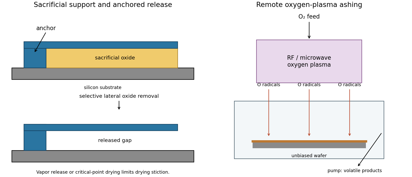
Selective sacrificial layer release and remote plasma ashing
. Details. 
Oxygen-plasma ashing, preferably a remote or downstream arrangement when low damage matters, removes organic photoresist chemically. Feed oxygen through a plasma source energized by radiofrequency or microwave power. Electron-impact dissociation generates reactive oxygen species; neutral radicals reach the wafer in a separate downstream region. Keep the wafer off a strongly biased driven electrode so energetic ion bombardment is much smaller than in directional reactive-ion etching. A barrel asher with shielded wafers is another chemical-stripping implementation.These equations represent radical production and an ideal complete-oxidation balance; actual exhaust can also contain CO and fragments. Pumping removes volatile products. Directional shape fidelity is unnecessary for blanket stripping, while access around surface relief and high chemical removal selectivity are useful. Monitor endpoint and wafer temperature, and verify removal with a witness surface. oxygen can oxidize exposed materials, charging can still damage sensitive structures, and inorganic or metal-containing residues may require a compatible separate clean. Ashing removes organic contamination; it is not a universal residue-removal step.[ref]
Physics of Microfabrication: Front End Processing, Lecture 20 by Massachusetts Institute of Technology. lecture transcript, discussion of barrel and parallel-plate plasma ashing, and comparison with RIE
Assume that each target's incorporated flux is proportional to its applied power over this operating range, and that the same composition convention is used throughout. The calibration gives at equal powers. Holding the A target unchanged while making the two incorporated fluxes equal therefore requiresThe B power decreases because B originally supplies more material. This linear magnetron sputtering approximation neglects power-dependent yield, target condition, resputtering and changes in sticking probability. A second composition measurement is the experimental check.
In the intended additive-deposition model, A originally contributes . At equal incorporated contributions, B also supplies , giving . Equivalently, the new total incorporated flux is times the calibrated total.
There is a composition-convention qualification. If the percentages represent mass flux and the mass density stays fixed, the preceding thickness calculation follows directly. If they instead represent atomic fractions, a constant atomic number density would justify the same result, whereas constant mass density alone does not. With atomic masses and constant mass density, the ratio would beThe PDF does not specify atomic versus mass percentages or the two elements. Thus 1.54 nm/s is the intended common flux-to-thickness approximation, and the formula above states the additional dependence if atomic fraction and constant mass density are meant literally.
Approximate each source as localized, keep the angular factors unchanged and use inverse-square flux dilution. The increased distance givesThis carries the composition/thickness convention of the previous answer. A greater source distance reduces fractional distance and angle variation across a given substrate, improving composition uniformity at the cost of rate. A real magnetron sputtering target is extended, with an angular emission distribution, and gas scattering can change the distance law; this is an estimate rather than a calibrated prediction.
Articles by others on the same topic
There are currently no matching articles.