Take a two-dimensional conducting sheet in the plane with magnetic flux density and electric current density along . Moving carriers feel the transverse Lorentz force . They accumulate at opposite edges, producing a transverse electric field until its force balances the magnetic deflection:For the transverse-voltage convention , this gives andThe Hall effect therefore measures carrier sign as well as density in the single-carrier approximation: electrons give the opposite transverse-voltage sign from positive carriers. Some tensor conventions call rather than ; the physical sign is fixed by the stated lead and field directions.
The Hall voltage is the integral of this transverse electric field across the sample width. In a three-dimensional slab of thickness , its magnitude is ; for a sheet, use the sheet number density and omit .
In the classical single-carrier model,for a two-dimensional sheet. The curve is a straight line through the origin, with its sign determined by the carrier charge and the voltage convention. The sheet Hall coefficient has units , consistent with the numerical slope used later.
The classical transverse response is not quantized. With carrier density and scattering parameters fixed, reversing reverses the transverse signal. Several carrier populations can produce a nonlinear classical curve, so straight-line behaviour here uses the stated single-population approximation rather than being a property of every conductor.
The integer quantum Hall effect requires a conducting two-dimensional electron gas with well-resolved Landau levels. In the simple parabolic-band model their orbital spacing isLow temperature and sufficiently low disorder broadening are needed so that and the relevant level width are small compared with this spacing. A high-mobility sample with is therefore useful.
Some disorder has a constructive role: localized states between extended Landau-level states allow the Fermi energy to move through a range of carrier populations while the transport response stays on a plateau. The longitudinal response is then very small and the transverse response is quantized. Whether odd or only even integer plateaux are resolved also depends on whether spin splitting is resolved.
On an integer plateau the sheet transverse resistivity has magnitudewhere the integer counts occupied resolved quantum Hall edge states. Increasing at fixed sheet density reduces the Landau filling factor . The observed trace is therefore a staircase toward larger , with transitions between plateaux rather than the classical straight line. In the plateau regions ; dissipative peaks occur at transitions.
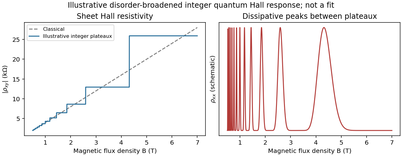
Classical Hall line and illustrative integer quantum Hall plateaux
. Original schematic responses, with the classical slope fixed by the later calculation. Plateau widths and dissipative peak shapes are illustrative rather than fitted to an experimental trace. Source. Details.
It is not correct to demand an exactly integer value of everywhere along a finite-width plateau. Localization accommodates changes in total population without changing the number of extended current-carrying channels. If spin remains unresolved, the usual spin-degenerate sequence contains even integers rather than every integer.
Using the magnitude of the classical slope,The Landau filling factor at isUnder the convention that the “last Landau level” means the last resolved spin branch, its degeneracy per area is . Setting givesAbove this threshold all carriers fit into that lowest resolved branch, which is partially filled when .
There is a spin convention to state explicitly: if “Landau level” instead means one orbital level with unresolved twofold spin degeneracy, its capacity is , and all carriers first fit into orbital index at , where . The slope alone determines and , but does not specify the spin splitting.
The giant magnetoresistance mechanism is spin-dependent conduction through the two ferromagnets. Exchange splitting gives majority and minority bands different density of states values at the Fermi energy. Scattering into those bands, together with interface scattering, produces different resistances for the two spin channels. The relevant quantity is the spin-dependent transport/scattering rate, not simply a count of all available states.
For parallel layer magnetizations, one global spin channel encounters relatively weak scattering in both Co and NiFe, providing a low-resistance path. For antiparallel magnetizations, each global spin channel encounters one more strongly scattering ferromagnet, so both paths are comparatively resistive. The channels conduct in parallel while each crosses the layers in series. This is current-perpendicular-to-plane magnetoresistance, because the current crosses the interfaces.[ref]
Nobel Lecture: Origin, development, and future of spintronics by Albert Fert. Spin-dependent conduction and the distinction between CPP and CIP transport
In the simplest two-current resistor model, with equal magnetic layers having channel resistances and spacer resistance per channel,Real Co/NiFe layers need not have equal parameters, but the same-sign spin asymmetries normally give . Their different magnetic coercivities allow the two configurations to be selected separately.
Assume NiFe is the softer layer, with , and that interlayer coupling is weak enough to permit separate reversal. Starting at large negative , both magnetizations point in the same direction and . During an increasing-field sweep:
- At , NiFe reverses while Co does not: the state is antiparallel and the resistance rises to .
- At , Co also reverses: the state becomes parallel and the resistance returns to .
On decreasing from positive saturation, the high-resistance window instead lies between and . Thus the two sweep directions give displaced rectangular high-resistance windows, not a single reversible resistance peak centered on zero.
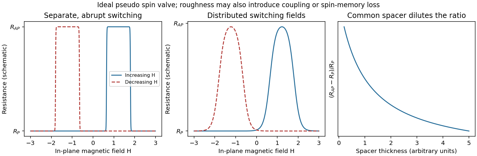
Pseudo spin-valve resistance loops, distributed switching and spacer dilution
. Original illustrative curves. Separate coercive fields create an antiparallel window on each sweep. The middle panel isolates switching-field broadening; its retained peak height is not a claim that real roughness leaves the GMR amplitude unchanged. Source. Details.
If Co were the softer layer, the sequence of layer labels would be exchanged. A continuous spacer and sufficiently weak coupling are additional assumptions: negligible surface roughness alone does not guarantee independent switching at every Cu thickness.
Specify the magnetoresistance ratio as . Increasing a continuous Cu spacer adds spin-independent series resistance. Even when remains below the spin diffusion length, this dilutes the ratio; spin information need not be destroyed to reduce the percentage signal. In the illustrative two-current resistor model,which decreases as increases. The absolute difference also decreases in this model. At a fixed bias current, the measured voltage contrast is .
For comparable to or greater than the spin diffusion length, additional spin relaxation further suppresses the contrast. At the other extreme an ultrathin or discontinuous Cu layer can introduce direct magnetic coupling or pinholes, preventing a fully antiparallel state. Thickness-dependent interlayer coupling can therefore make the very-thin-spacer trend nonmonotonic; a universal exponential law does not follow from the supplied assumptions.
Roughness can produce a distribution of local switching fields and nonuniform reversal. The abrupt edges in the ideal pseudo spin valve loops then become rounded or sloping, the antiparallel plateau becomes less flat, and overlapping layer-reversal distributions can narrow or partly eliminate the clear high-resistance window. The middle panel of the original diagram illustrates only this broadening mechanism.
Correlated roughness on the two interfaces can also introduce orange-peel coupling, a magnetostatic coupling that favors parallel alignment. Such coupling shifts switching fields and can suppress independent reversal. Sufficiently severe roughness or pinholes can have a similar qualitative effect by directly coupling the ferromagnets.
Changes in amplitude require care. Some spin-dependent interface scattering contributes to giant magnetoresistance, so a small increase in roughness is not guaranteed to lower the signal monotonically. Intermixing, spin-flip scattering and an incompletely antiparallel state generally reduce useful contrast. The detailed width, displacement and height of therefore depend on how the interfaces become rough, rather than on a single roughness number.
Two practical approaches retaining Co and NiFe are:
- Improve the spin-selective interfaces: control deposition and intermixing, avoid oxidation or magnetic dead layers, and reduce pinholes and spin-flip defects. The aim is large majority/minority transport asymmetry with low spin-memory loss, rather than merely the smallest total resistance.
- Optimize the Cu thickness and electrical stack: use the thinnest continuous spacer that still allows independent layer reversal and remains well below its spin diffusion length; reduce extraneous contact or lead resistance. This preserves a full antiparallel state and limits spin-independent dilution of the measured magnetoresistance ratio.
Increasing magnetic-layer thickness toward the useful spin-dependent-scattering scale can be another optimization, but growth beyond the relevant spin diffusion scale eventually gives diminishing returns. Merely increasing the bias current increases the readout voltage and possible heating; it does not, by itself, increase the intrinsic giant magnetoresistance ratio.
Articles by others on the same topic
There are currently no matching articles.