Choose the phasor convention and similarly for the electric current. In a linear sinusoidal steady state, differentiation becomes multiplication by , and complex impedance is . Kirchhoff's current law and Kirchhoff's voltage law then become algebraic equations that retain both amplitude and phase information.
For a resistor, , so . For a capacitor, , while an inductor obeys . ThereforeThe resistor's electric potential difference and current are in phase. The inductor's electric potential difference leads its current by ; the capacitor's current leads its electric potential difference by . Replacing by conjugates every impedance but leaves these physical lead-and-lag statements unchanged. The phasor method describes the steady state; switch-on transients must be added separately when initial conditions are relevant.
A series connection has the same electric current through each element, so complex impedances add:For , define . ThenAbove resonance, the circuit is inductive and electric potential difference leads current; below resonance it is capacitive and electric potential difference lags current. Atthe inductive and capacitive reactances cancel and is purely resistive. The same resonance condition holds for an ideal series circuit independent of the drive amplitude.
A parallel connection has the same electric potential difference across each element, so the electrical admittances add. With and ,For a prescribed sinusoidal current, . Thus the voltage-minus-current phase isBelow the circuit is inductive, so electric potential difference leads current; above it the circuit is capacitive, so electric potential difference lags current. At , the reactive branch currents cancel, and . This is the impedance maximum for positive finite , whereas the series circuit has its impedance minimum at the same frequency. It does not mean that either individual reactive branch current vanishes.
The source's variable inductor and variable resistor are in parallel. Let their combined complex impedance beUse the left and right source terminals as the drive nodes. The upper divider has arms and ; the lower divider has arms and . At bridge balance, the detector draws no electric current and the divider midpoint electric potential differences agree, soSubstitution and cancellation at a nonzero drive frequency giveEquating real and imaginary parts yieldsThe first expression has units of resistance and the second units of inductance. Both are independent of the drive amplitude and, for ideal frequency-independent components, of the chosen nonzero drive frequency. At zero frequency the ideal inductors short their arms and the cancellation would not be valid as a measurement of .
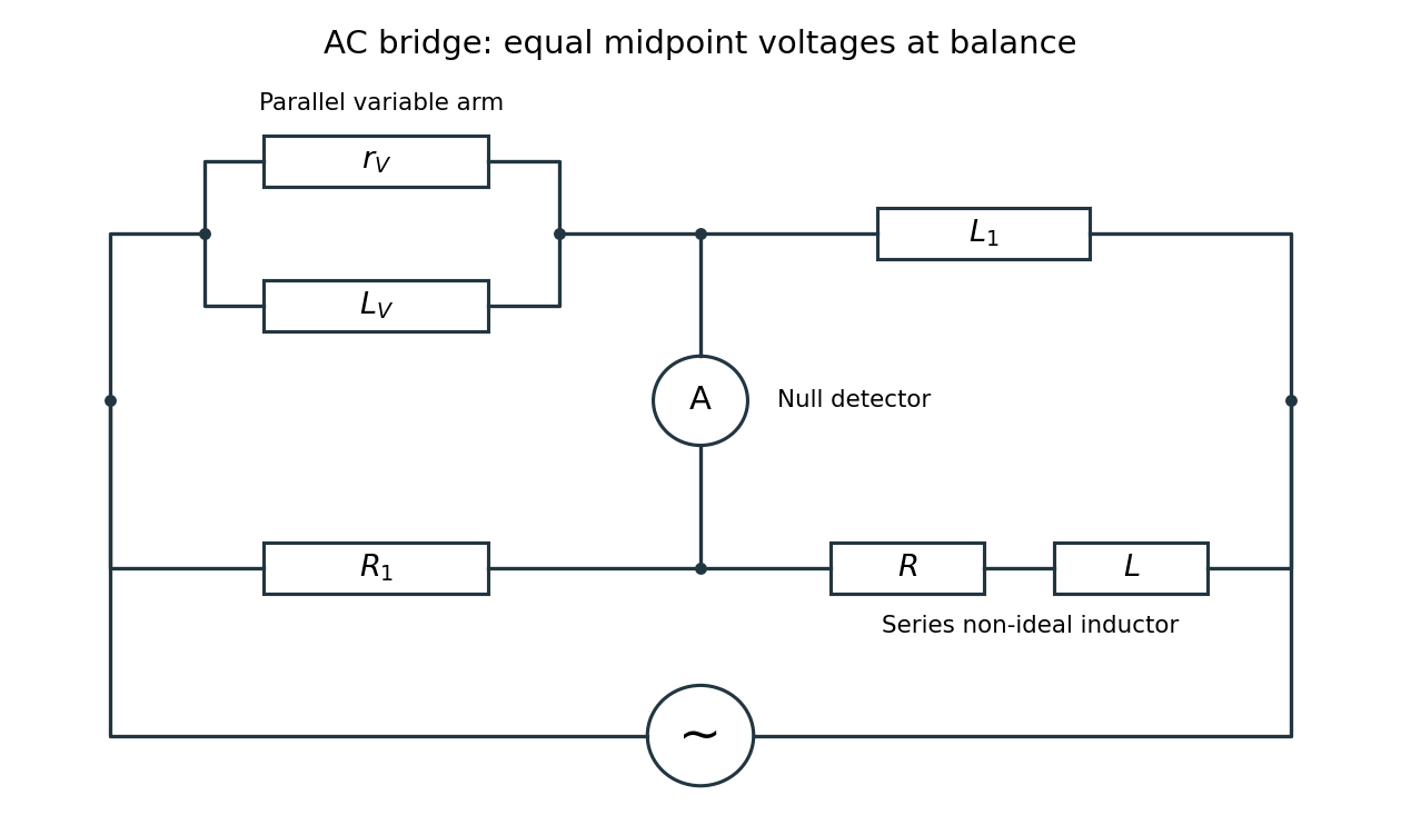

Two applications are precision comparison of an unknown electrical resistance with calibrated standards in a Wheatstone bridge, and detecting small resistance changes in a strain gauge or resistance thermometer. Alternating-current bridges additionally compare capacitance, inductance and dielectric losses; this particular bridge determines the two parameters of a non-ideal inductor from a null measurement.
Articles by others on the same topic
There are currently no matching articles.