Use a synchronous binary counter with three positive-edge-triggered D flip-flops, all driven by the same clock signal. Write their outputs , with the least significant bit. The next-state Boolean functions areImplement these with one NOT gate, two exclusive or gates, and one AND gate. Connect each to its corresponding D flip-flop; its output is address line . A reset input clears all three flip-flops to zero, so the first selected sensor is sensor zero.
The state sequence isThe low bit toggles at every clock edge, the middle bit toggles exactly when the old low bit is one, and the high bit toggles exactly when both old lower bits are one. These are precisely the carry conditions for incrementing a three-bit binary representation. Every possible state belongs to the cycle, so there is no unused state requiring recovery. Choose a clock period allowing the combinational logic to settle before the next capture.
For data inputs and selection bits , use a three-to-eight binary decoder. Its output is the minterm that is one exactly when the selection equals the three-bit binary representation of . For example,Gate each data input with its decoded selection using an AND gate, then combine all eight results with an OR gate:Exactly one is asserted, so for the selected , regardless of the other data inputs. A direct implementation uses three shared NOT gates, eight three-input AND gates for the binary decoder, eight two-input AND gates for the data, and one eight-input OR gate. Equivalently, combine each decoder term with its data input in one four-input AND gate. Larger logic gates may be built from two-input ones.
Use eight parallel 8:1 multiplexers and one shared three-bit binary counter. If is bit from sensor , connect to multiplexer . Connect all selection inputs to the binary counter outputs. Then data line carries , so all eight data lines belong to the same selected sensor. Send the three counter outputs to the receiver as the address lines as well.
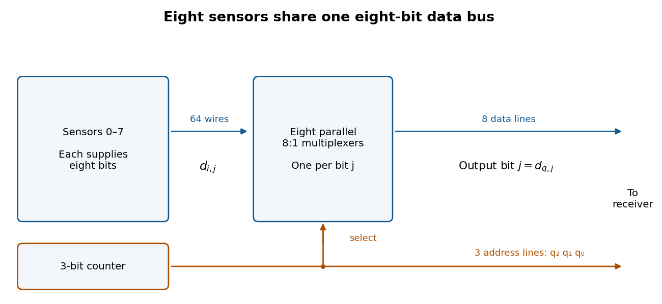

After reset the receiver sees sensors , one per clock period. Sample the data and address only after the binary counter and multiplexers have settled, for example on the opposite clock edge with a sufficiently long clock period. Changing addresses can otherwise cause transient logic hazards. The transmitter uses eleven signal lines, apart from any shared clock or reset connection.
Use an eight-bit modulo-256 binary counter, eight 256:1 multiplexers, eight data lines and eight address lines. Thus there are sixteen signal lines, apart from clock and reset, and a full scan takes 256 clock periods. The counter next-state equations generalize toA 256:1 multiplexer for one data bit can be made hierarchically: 32 first-stage 8:1 multiplexers select within eight-sensor groups using ; four second-stage 8:1 multiplexers select groups using ; one final 4:1 multiplexer selects using . A final 8:1 multiplexer also works if one select input is fixed to zero and only four data inputs are used. Repeat this network eight times, sharing all selection lines. Allow for the extra propagation delay when choosing the clock period.
Articles by others on the same topic
There are currently no matching articles.