A single-fibre tensile test pulls one material fibre between grips while measuring axial force and extension over a defined gauge length. A load cell supplies force information; a direct specimen-extension measurement or a corrected crosshead displacement supplies extension. With initial area and initial gauge length , the conventional engineering stress and engineering strain areThe initial proportional slope estimates Young's modulus; a changing local slope is a tangent modulus. The area and displacement conventions must accompany that result.
The glass- and carbon-fibre study by Rajnish Kumar, Lars Pilgaard Mikkelsen, Hans Lilholt and Bo Madsen used a semi-automated single-fibre machine and compared stress-strain-based modulus determinations.[ref]
Understanding the mechanical response of glass and carbon fibres: stress-strain analysis and modulus determination by Rajnish Kumar and others. Public primary abstract, apparatus and modulus analysis
Its dataset contains individual tensile curves, gauge-length groups and test-setup compliance calculations.[ref]Single fiber tensile test - Glass and Carbon fibers by Rajnish Kumar and others. Description, Data/Results files and Compliance spreadsheets
For an original ideal calculation, take a circular strand of diameter and . Its area is . A force increment produces measured crosshead travel . Suppose independently established machine compliance is , with no grip slip and the same deforming specimen length as . ThenUsing the uncorrected travel would instead give . These chosen increments represent a proportional segment, not measured dataset values or a complete uncertainty analysis.
Check grip slip, specimen alignment and the force zero before interpreting the slope. An irregular area cannot automatically be replaced by a circular area from one apparent diameter. A vibroscope offers another route to fibre-area estimation through vibration under tension.[ref]
Vibroscope method for determination of cross-sectional area of glass and carbon fibres – Experiments and analyses by Bo Madsen and others. Public abstract, area estimation from tensioned-fibre frequency measurements
Preserve the original force and displacement records so corrections and area assumptions remain inspectable.The Favimat+ fibre testing machine combines measurements on individual material fibres, including a single-fibre tensile test and vibroscopic estimation of linear mass density. Its useful feature is the association of the force-extension record with a measurement of the same strand, rather than with a batch-average geometry.
In the reported glass- and carbon-fibre study, a magazine held the prepared strands and a robotic device transferred each to the grips. The built-in vibroscope used acoustic excitation and a frequency sweep to identify resonance; a load cell measured tension and grip separation supplied the suspended length. Tensile measurements followed vibroscope measurements on the same still-gripped fibre.[ref]
Vibroscope method for determination of cross-sectional area of glass and carbon fibres – Experiments and analyses by Bo Madsen and others. §§3.2–3.3, semi-automated handling, acoustic resonance measurement and same-fibre tensile sequence
An original pairing example shows why strand identity matters. Suppose two strands have independently established material areas and , and each carries . Their engineering stresses areUsing the common mean area would assign both , concealing the difference. These are chosen values, not measured instrument data.
Frequency first supports a mass-per-length estimate under the vibration model; converting it into area also needs compatible mass density and deformation conventions. The vibroscope area estimator explains that inference and its limitations. Force and displacement readout resolution are likewise not complete statements of measurement uncertainty or specimen extension: machine compliance and grip motion must be assessed when extracting a modulus.
A vibroscope measures the vibration of a tensioned material fibre. In fibre testing, the measured fundamental frequency, suspended length and applied tension can be used to estimate linear mass density; known mass density then permits an area estimate. The physical measurement complements the single-fibre tensile test, whose conversion from force to engineering stress requires cross-sectional area.
The 2024 study by Bo Madsen, Rajnish Kumar and Hans Lilholt compared area-analysis procedures using measured frequencies of tensioned glass and carbon strands.[ref]
Vibroscope method for determination of cross-sectional area of glass and carbon fibres – Experiments and analyses by Bo Madsen and others. Public abstract, frequency measurements and simple/direct/iterative area analyses
A practical arrangement holds a known strand length, applies a known tension, excites small transverse oscillations and detects the frequency of its response. The supports and identification of the vibration mode enter the interpretation.For an original idealization, treat the strand as a uniform flexible string with fixed endpoints, length , tension and linear mass density . Its wave speed is and its fundamental wavelength is , giving the vibroscope area estimatorThe string wave-speed and fixed-end standing-wave relations supply this model.[ref]
University Physics Volume 1 by William Moebs and others. §16.3, wave speed on a stretched string; §16.6, fixed-end standing-wave modes
Choose , , and . The model gives and . Only if a circular area is assumed does this correspond to diameter .
These are stipulated model values, not published fibre data. Checking several tensions tests the predicted proportionality of to . Finite bending resistance, uncertain effective length and changes in strand dimensions under tension can invalidate the flexible-string estimate. A resonance peak alone does not establish that all of its assumptions hold.
The vibroscope area estimator converts the fundamental frequency of a tensioned material fibre into a cross-sectional area through a mechanical model. For a uniform flexible strand of length , positive tension , linear mass density and mass density , the fixed-end string relation givesThe second equation uses : the frequency first identifies mass per length under the stated tension, and a chosen mass density then converts it into area. Circular geometry is needed only to infer a diameter from that area.[ref]
University Physics Volume 1 by William Moebs and others. §16.3, equation 16.8, string wave speed; §16.6, fixed-end standing-wave modes
The experimental study by Bo Madsen, Rajnish Kumar and Hans Lilholt used a Favimat+ fibre testing machine. Acoustic waves excited the strand, and a frequency sweep plus a polynomial fit located the resonance peak. A load cell measured tension, while grip separation supplied . The reported frequency range was 500–4000 Hz, with an estimated resolution of 0.1 Hz; the stated force and length readout resolutions were and . Those readout resolutions do not themselves specify the estimator's full measurement uncertainty.[ref]
Vibroscope method for determination of cross-sectional area of glass and carbon fibres – Experiments and analyses by Bo Madsen and others. §3.2, apparatus, acoustic excitation, swept-sine/polynomial peak determination and measurement resolutions
The area and mass density must refer to the same loaded or reference configuration. The companion theory derives volume and area corrections for recovering an untensioned reference area from the tensioned measurement.[ref]
The vibroscope area uncertainty follows locally by logarithmic differentiation:Treat the small input errors as independent random variables, and let each denote the corresponding standard uncertainty. First-order uncertainty propagation then givesCorrelated inputs require their covariances as well. Four independent 1% relative standard uncertainties give for the area. A systematic 1% overestimate of frequency alone instead multiplies the area estimate by : it produces about a 1.97% underestimate.
Bending resistance can also increase the observed frequency. The companion theory paper models fully clamped supports and derives the corresponding frequency equation and deformation corrections.[ref]
Vibroscope method for determination of cross-sectional area of glass and carbon fibres - Theory and further development by Bo Madsen and others. §§2.1–2.2, beam equation and clamped-end conditions; §§5–6, corrections for the tensioned fibre
An independently derived, simply supported example isolates the bending-stiffness bias in the vibroscope area estimator. Let be the filament bending modulus and impose zero deflection and zero bending moment at each endpoint. Substituting into the tensioned Euler-Bernoulli beam equation givesWith , the uncorrected flexible-string estimate satisfies . At , it is 9.09% too small. The same model yields two-mode separation of tension and bending stiffness:For and , the predicted mode ratio is , ranging from 2 toward 4. These identities belong to the simply supported model; clamped grips require their own boundary conditions. Neither a single resonance peak nor an assumed diameter establishes the appropriate support, density or bending correction.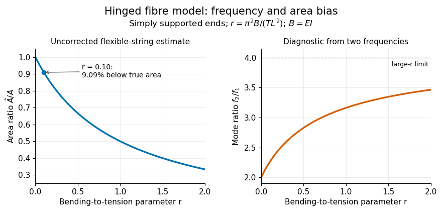
Original simply supported fibre model: bending resistance lowers the uncorrected area estimate and changes the ratio of the first two frequencies.
Details. 
Bending-stiffness bias in the vibroscope area estimator occurs when bending resistance raises a strand's frequency but its area is inferred with a flexible-string model. In the independently derived simply supported beam model in vibroscope area estimator, let be the bending rigidity, the tension and the length. The dimensionless ratio and area error areHere is the actual area in the model's measurement configuration. The parent article derives this relation; no circular-area assumption is needed for the ratio once is specified.
For an original example, choose and . The uncorrected estimate is , twenty percent below the model area. Doubling only , with the same , and material configuration, divides by four. The new ratio is , giving , about 5.88 percent low. A length-dependent discrepancy is therefore a useful diagnostic to investigate, rather than evidence that the material area itself changed.
The boundary conditions are essential. Simply supported endpoints impose zero displacement and zero bending moment. The companion experimental theory instead treats fully clamped endpoints, with zero displacement and slope, and derives its own frequency and deformation corrections.[ref] The displayed correction cannot be transferred unchanged to that apparatus.
Two-mode separation of tension and bending stiffness supplies another check within the same simply supported model. A model correction for bending bias also remains distinct from the standard input uncertainties treated in vibroscope area uncertainty.
Two-mode separation of tension and bending stiffness uses two identified transverse eigenmodes to separate coefficients that a single resonance cannot determine independently. For the uniform simply supported beam model derived in vibroscope area estimator,Thus plotting against gives an intercept associated with tension and a slope associated with bending. Frequencies alone identify these ratios; determining dimensional and also requires the remaining scale quantities.
An original exact example takes and . The two transformed values are and at and . Their difference givesHence . Using the first mode as if would use instead of for the tension coefficient; the corresponding area correction is a factor under this model.
Two observations fit two free coefficients, so that fit alone does not validate the model. A third identified mode should satisfy , or , in this example. Repeated measurements and another mode can test consistency.
For and , the same model requires . A ratio outside that range contradicts at least one assumption or the mode assignment. Actual clamped grips require the clamped-end frequency model described in the companion theory.[ref]
Vibroscope method for determination of cross-sectional area of glass and carbon fibres - Theory and further development by Bo Madsen and others. §2.2, clamped-end boundary conditions and frequency equation
Do not label arbitrary neighbouring resonance peaks as modes one and two without additional evidence.Vibroscope area uncertainty quantifies uncertainty in an area inferred from a vibration model and its measured inputs. For the flexible-string vibroscope area estimator, length and frequency enter with inverse-square dependence, whereas tension and density enter to the first power. The parent article gives the full first-order propagation formula. A measurement uncertainty budget records the input standard uncertainties, their sensitivities and any correlations.[ref]
Guidelines for Evaluating and Expressing the Uncertainty of NIST Measurement Results by Barry N. Taylor and Chris E. Kuyatt. §5.1; AppendixA, equationA-3, sensitivity coefficients and covariance terms
For an original independent-input example, stipulate relative standard uncertainties of in tension, in density, in length and in frequency. After applying the sensitivity coefficients, their relative area contributions are . Combining their squares givesFor a stipulated estimate , this is . Density contributes of the combined variance. Improving the frequency readout alone would therefore make little difference to this budget. Reducing the density contribution from to instead gives overall.
These input uncertainties are assigned model values, not the readout resolutions quoted for the Favimat+ fibre testing machine. A resolution increment does not determine a standard uncertainty without a model for the associated error. Correlated inputs require covariance terms; their signed sensitivities can either reinforce or cancel contributions.
The budget also presumes an adequate measurement model. Bending-stiffness bias in the vibroscope area estimator, uncertain supports or deformation conventions may require a correction and additional uncertainty terms. Increasing the numerical precision of the frequency does not repair a wrong physical model.
Articles by others on the same topic
There are currently no matching articles.