A material fibre is a long, slender physical strand: its length is large compared with its transverse dimensions. The geometry is shared by materials with different roles. Carbon fibres and glass fibres can reinforce a composite material, while an optical fibre guides light. The material's properties, the strand dimensions and the way strands are assembled all affect its response.
A single-fibre tensile test grips one strand, measures its axial force and extension over a specified gauge length, and uses its cross-sectional area to obtain stress and strain. A 2020 study used a semi-automated instrument to characterize glass fibres and carbon fibres through their stress-strain curves and inferred moduli.[ref]
Understanding the mechanical response of glass and carbon fibres: stress-strain analysis and modulus determination by Rajnish Kumar and others. Public primary abstract: single-fibre apparatus and modulus analysis
Its public dataset supplies individual tensile curves at several gauge lengths, summary sheets and calculations of test-setup machine compliance.[ref]Single fiber tensile test - Glass and Carbon fibers by Rajnish Kumar and others. Dataset description, gauge-length groups and compliance files
This matters because crosshead displacement can include deformation of the apparatus as well as extension of the material fibre; its slope alone need not give the specimen's Young's modulus.An original ideal model shows why making thinner strands changes some responses more strongly than others. Keep total material cross-sectional area , length and Young's modulus fixed. Compare one solid circular rod with identical circular fibres, each of radiusFor axial loading, grip every strand so that all undergo the same extension . Each supplies force , and adding the forces gives the axial stiffnessindependent of under these assumptions. This is the uniform-bar linear elasticity relation applied to parallel strands.
Now make a separate pure-bending comparison of an unbonded material-fibre bundle. Allow longitudinal sliding, neglect friction, and let each strand bend about its own neutral axis with the same curvature . A circular strand has second moment of area and filament bending modulus . Its bending moment is in the small-deformation model.[ref]
Stresses in Beams by David Roylance. Normal Stresses, equations3–6, pp.2–4: linear-elastic moment-curvature relation
Adding those moments gives the bending rigidity of an unbonded fibre bundle:Each material fibre has its own neutral axis, which is crucial to this calculation. Bonding strands together transfers shear stress and couples their axial deformation; the independent-strand sum then ceases to describe the assembly. In a reinforced composite material, that coupling is part of fibre-matrix load transfer.For chosen , and , both axial specimens have . At , each radius is approximately , and the independent-bending value is compared with for the solid rod. The parameters are stipulated for this model; counts material and excludes spaces between strands.
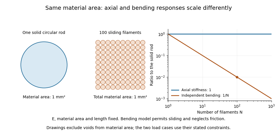

A useful mechanical comparison therefore records which material fibres are gripped, whether they can slide, their arrangement and the loading direction. Equal material quantity alone does not determine an assembly's stiffness, and small filament bending modulus does not imply small axial Young's modulus.
An unbonded material-fibre bundle collects separate material fibres without continuously bonding neighbouring strands together. Contact and friction may still transfer force, so unbonded does not automatically mean freely sliding. The response depends on which strands are gripped, their alignment, slack and whether inter-fibre sliding is permitted.
For straight strands of common length , let both end fixtures impose the same small extension on every strand. Under linear elasticity, strand carries , soThis follows by applying the uniform-bar axial stiffness relation to the strands in parallel.[ref]
Structural Stiffness Concept by TU Delft OpenCourseWare. Axial member relation and material-versus-geometrical contributions
Equal extension here is an end-loading condition. It does not require continuous bonding, nor does it describe the separate freely sliding bending experiment in bending rigidity of an unbonded fibre bundle.The material cross-sectional area excludes gaps. An envelope enclosing the bundle can have larger area . Define the bundle material area fraction . For identical moduli , inferring a modulus from the envelope and the measured axial stiffness givesAs an original example, four circular strands of radius have . Stipulate an envelope area , and . Then , and . That lower effective value does not mean the strand material has changed.
A useful tensile comparison counts the engaged strands, measures their areas and checks that the fixtures actually impose the assumed extension. A loose or broken strand changes the load-bearing area even if the outer envelope barely changes. Individual strand properties can be characterized by a single-fibre tensile test; neither envelope dimensions nor a bundle slope alone identifies every strand's Young's modulus.
Inter-fibre sliding is relative tangential motion between contacting material fibres. It is distinct from stretching both strands together: equal axial extension can occur with no relative motion at a contact, while bending can require strands to exchange longitudinal position. For local strand displacements and and a contact tangent , the contact slip displacement isThe contact and the sign of must be specified. Contact friction can oppose changing even in an unbonded material-fibre bundle.
An original bending geometry makes the required relative travel visible. Consider two nearby reference paths of radii and , turning through the same angle , measured in radians. Their arc lengths differ byFor chosen separation and turn angle , this mismatch is . If the strands remain inextensible while following those paths, material must feed through the ends to accommodate the difference. Fixing both ends of equal-length strands to remain aligned instead imposes additional strain or a change in the assumed geometry.
This explains the importance of a separate neutral axis for each strand in the freely sliding model for bending rigidity of an unbonded fibre bundle. Bonding imposes longitudinal compatibility and can require axial tension in some strands and compression in others. The usual beam model relates the resulting axial strain to position relative to a common neutral axis.[ref]
A useful mechanical test marks neighbouring strands, bends the assembly while allowing end travel, and measures their relative mark positions. Repeating the bend with constrained ends tests a different loading condition. Record contact loading and bend history: an absence of observed slip at small applied force does not by itself establish a permanent bond.
The contact slip displacement is signed relative tangential displacement at a specified contact. For small motions in a fixed local frame, let be a tangential unit vector and let describe the two contacting surfaces. ThenThis scalar product extracts relative motion along the contact. The corresponding relative normal displacement is a separate quantity controlling opening or closure. This local distinction matters for inter-fibre sliding: an entire bundle can move without adjacent material fibres slipping against one another.
As an original local example, take , and . The contact slip displacement is and the relative normal displacement is 0. Adding the same translation to both surfaces changes neither result. Reversing the orientation of reverses the sign of while preserving its magnitude. If the contact frame rotates substantially or different material points enter contact, relative tangential velocity must be evaluated in the current contact frame and integrated consistently; projecting one final global displacement difference onto a final tangent vector is not a general finite-motion formula.
Under the ideal dry-friction model, static friction can transmit tangential force while the local slip rate is 0. Sliding introduces kinetic friction; with constant normal force , its magnitude is , where is the coefficient of friction.[ref]
University Physics Volume 1 by William Moebs and others. §6.2, static-friction bound and kinetic-friction model, equations 6.1–6.2
The accumulated contact slip and the frictional dissipation from contact slip are therefore different from net signed displacement:The second expression follows from integrating the opposing frictional force over each increment of relative sliding; it assumes constant and . For a prescribed out-and-back slip from 0 to and back to 0, the final is 0 but . With stipulated and , the dissipated energy is . Zero net slip does not imply zero frictional dissipation.A simple measurement marks both surfaces close to a maintained contact, images their relative positions while tangential loading is varied, and resolves motion along the local contact direction. Measurement calibration converts image distances to lengths. Marks far from the contact can also move because the strands stretch or the fixtures deform; a grip-travel readout alone does not isolate contact slip displacement. Record both the signed motion and accumulated contact slip when comparing repeated bending cycles of an unbonded material-fibre bundle.
Frictional dissipation from contact slip is the irreversible loss of mechanical energy associated with relative sliding at a contact. In the ideal kinetic friction model, friction opposes the local slip velocity and has magnitude , with nonnegative coefficient and normal force . Its dissipated energy isThe work calculation and the distinction between signed and accumulated motion are developed in contact slip displacement. The kinetic-friction force law is an ideal physical model, rather than a universal description of every interface.[ref]
An original two-stage example keeps the loading history explicit. Let . Slide forward while , then backward while . The final signed slip is , the accumulated contact slip is , andThe two stages contribute and . Using the unweighted mean of the two normal loads would instead give ; the correct weighting follows sliding distance.
A physical measurement records relative motion close to the contact together with tangential force and normal loading. Integrating the opposing tangential force over the resolved sliding increments estimates the lost mechanical energy under the stated model. Force transmitted during ideal sticking, where local slip rate is zero, contributes no slip dissipation in that model, even if other parts of the apparatus deform. Grip travel and fixture mechanical compliance therefore must be distinguished from local sliding.
Accumulated contact slip measures the total distance slid at a specified contact, counting motion in either direction positively. For an absolutely continuous signed contact slip displacement in a consistently tracked local frame,It is the total variation of a function applied to the slip history. It differs from net slip , which can lose information through cancellation. Contact slip displacement explains the contact-frame convention and the connection to frictional dissipation from contact slip.
For an original piecewise-linear trajectory, suppose successive slip values are . Its net slip is , whileThe middle reversal contributes even though it moves toward smaller signed coordinates. Recording only the first and last values would report and miss eighty percent of the travelled distance in this stipulated history.
For exact samples at ordered times, the sum of absolute increments is a lower bound on the true accumulated motion; unobserved reversals can add distance between samples. The triangle inequality explains why inserting additional exact observations cannot decrease this sum. It equals the integral when the observed intervals contain no unresolved reversals and the path model is appropriate.
Measurement noise changes that conclusion about observed data. A truly stationary contact read as would acquire an apparent distance for positive . More samples can reveal real reversals while also accumulating readout noise. A useful imaging study therefore reports time resolution, length measurement calibration and the treatment of noise, rather than interpreting every absolute increment as physical sliding.
The bundle material area fraction is the fraction of a stated bundle envelope occupied by strand material in a specified transverse section:Here includes spaces between material fibres, while excludes them. Count each strand area once and state how the envelope is drawn. A tighter envelope can increase without adding material. For parallel prismatic strands and a constant envelope over common length , the corresponding volumes are and , so the volume fraction equals under those assumptions.
An original two-strand example shows why an average diameter is insufficient. Take circular strand radii and , inside a stipulated envelope of area . ThenReplacing both radii by their arithmetic mean would give and , underestimating the material area by twenty percent. Area depends on the mean squared radius, not merely the square of the mean radius.
For straight, equally strained strands of a common Young's modulus , the axial stiffness is . Dividing the measured rigidity by instead gives the envelope-based effective modulus , rather than the strand material's . This uses the uniform-bar relation applied to parallel strands.[ref]
Structural Stiffness Concept by TU Delft OpenCourseWare. Axial relation and distinction between structural geometry and material properties
A physical estimate can image a transverse section, establish measurement calibration for image lengths, identify the strand boundaries and calculate both areas from the same section. State section orientation: an oblique image is not automatically a perpendicular-area measurement. Distinguish spaces between strands from internal voids within a strand if the intended quantity is solid material area. Changes of envelope convention or classification must not be mistaken for changes in material quantity.
The bending rigidity of an unbonded fibre bundle relates total bending moment to curvature in a stated bending model. If slender material fibres slide longitudinally without appreciable friction, each bends about its own neutral axis. With the same imposed small curvature and no additional axial tension, strand contributes , givingHere is that strand's second moment of area about its own bending axis. The underlying linear elasticity relation is the beam moment-curvature law.[ref] Adding offset-area terms as though all strands shared one neutral axis would impose a different mechanical constraint.
An original two-strand comparison makes the difference quantitative. Take two identical circular strands of radius , with centres vertically separated by , bending in the plane containing their centres. Each has and . In the freely sliding model,For a separate idealization, bond the strands perfectly along their contact so they share a common neutral axis halfway between the centres. Neglect the bond's own area and compliance. Integrating squared distance from that common axis givesFor stipulated and , these are approximately and . At , the corresponding moments are and . Both specimens contain the same strand material; their ability to exchange longitudinal force differs.
A physical comparison would impose end rotations, permit the relative end travel required for inter-fibre sliding, and measure bending moment and curvature. Clamping every strand to identical end displacements, adding axial tension or allowing friction can change the response. The factor five above belongs to this two-strand geometry and ideal bond, not to every bundle. The equal-material subdivision model in material fibre makes a different comparison with a solid circular rod.
Articles by others on the same topic
There are currently no matching articles.