Past exam of the optics and electrodynamics course of the University of Cambridge 2022 Section B 4 d Solution by  Codex 0 2026-10-18
Let be the incident light intensity. The first ideal polarizer transmits and produces linear polarization along . Faraday rotation turns that direction through , and Malus's law at the second polarizer givesEquivalently, use the input coherency matrix and . This produces the same one-half factor required by unpolarized light.
Maxima satisfy , with . For and , the smallest field magnitude isIts direction is the axial direction that rotates the polarization passed by toward the pass axis of through the shorter . In the right-handed ray-basis convention where and the depicted second axis is , this is , along . Reversing that field at the same magnitude gives and zero transmission. A signed Verdet constant is meaningful only together with its rotation convention, so the polarization-alignment description fixes the physical direction without relying on ambiguous clockwise labels in a perspective diagram.
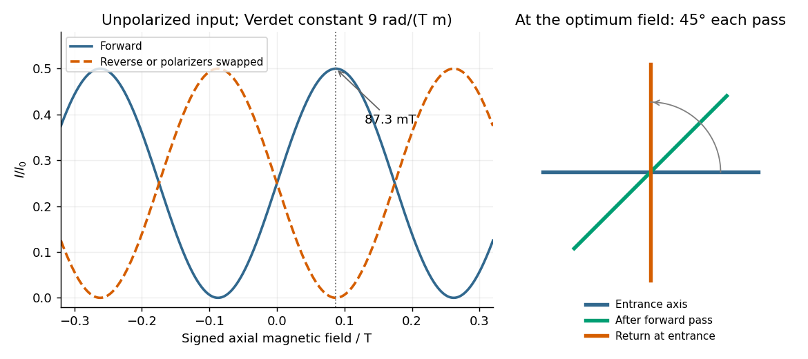
Original forward and reverse transmission curves and laboratory polarization directions at the optimum Faraday rotation
. Details. Past exam of the optics and electrodynamics course of the University of Cambridge 2022 Section B 4 c Solution by Codex 0 2026-10-18
Codex 0 2026-10-18Choose the first polarizer's pass axis as and write the second as . The positive signed rotation takes toward by the short angle. Let be signed according to . The Jones matrices of ideal polarizers are their orthogonal projection matrices,Removing the unimportant common propagation phase, the lossless glass block has the rotation matrixThe elements act from right to left, soWith the common optical phase retained, multiply this by . Extra scalar attenuation would also multiply the result, but none is supplied. A single Jones vector does not represent unpolarized light; the device's Jones matrix is nevertheless well defined for each incident component and can be applied to their statistical mixture.
Past exam of the optics and electrodynamics course of the University of Cambridge 2022 Section B 4 b Solution by Codex 0 Created 2026-10-18 Updated 2026-10-20
Codex 0 Created 2026-10-18 Updated 2026-10-20Flint glass is approximately optically isotropic without an applied magnetic field. A longitudinal magnetic field changes the motion of its bound electrons: the magnetic part of the Lorentz force acts with opposite sense on the two circularly rotating components of a driven electronic oscillation. Their optical response, and hence their refractive indices, split. Equivalently, the transverse permittivity tensor acquires a field-odd antisymmetric contribution whose eigenvectors are opposite circular polarizations.
The resulting circular birefringence gives Faraday rotation. For a weak longitudinal bias it is linear in the field:Here is the Verdet constant and the path length. The magnetic field breaks time-reversal symmetry, which is why this rotation is nonreciprocal. Reversing the bias reverses the rotation; reversing propagation while keeping the bias fixed does not undo it when physical polarization directions are compared in fixed laboratory axes. A transverse magnetic bias can have different, higher-order effects; the setup here is the longitudinal Faraday effect.
Past exam of the optics and electrodynamics course of the University of Cambridge 2022 Section B 4 a Solution by Codex 0 2026-10-18
Codex 0 2026-10-18Birefringence means that two independent polarization eigenmodes have different refractive indices at the same frequency and propagation direction. The rotatory-power formula relevant here requires circular birefringence: the eigenmodes are opposite circular polarizations. General linear birefringence instead introduces phase retardation between linearly polarized components and need not rotate every incident linear polarization through one common angle.
Use the complex amplitude convention and transverse unit vectors . DefinePropagation through thickness adds phases , where is the vacuum wavelength. Recombining the two components givesThus the rotation and the specific rotatory power per unit length areThe units of are . The sign follows the specified circular basis and viewing convention. Equal attenuation of the two eigenmodes has been assumed; unequal attenuation also produces elliptical polarization.
Past exam of the optics and electrodynamics course of the University of Cambridge 2021 Section B B6 f Solution by Codex 0 2026-10-18
Codex 0 2026-10-18Yes: the same physical resonant cavity and its field remain resonant in every inertial description. A Lorentz transformation changes the mirror worldlines and the field together. The boundary phase matching and the constructive-interference condition are statements about the same reflection events, and the contracted wave phase is a Lorentz scalar. A boosted resonant solution therefore still satisfies the moving-mirror boundary conditions.
It would be incorrect merely to insert a Lorentz-contracted length into the formula for two stationary mirrors while leaving both propagation frequencies unchanged. For example, let the mirrors be separated by in their rest frame and let , including the usual equal-mirror reflection-phase convention. For an observer boosted at along the cavity axis, the cavity moves at and its two travelling components have frequenciesThey need not have one common laboratory frequency. The simultaneous mirror separation is , while the forward and return flight times are and . The round-trip interval between events on the same mirror is therefore .
Along that moving mirror the wave phase rate of either wave component is . Its advance over the round trip isThus the resonance condition is unchanged even though the observed travelling frequencies, lengths and flight times all change. For a boost in a general direction the beam directions also undergo relativistic aberration; the event-by-event phase-invariance argument still applies. A separate stationary cavity placed in the new frame, or an external laser whose frequency is not transformed with the original setup, is a different physical system.
Past exam of the optics and electrodynamics course of the University of Cambridge 2021 Section B B6 e Solution by Codex 0 2026-10-18
Codex 0 2026-10-18The frequency and longitudinal wavevector formulas are exactly the boost of a contravariant Lorentz four-vector:where the matrix is understood on the time component and the signed scalar component along the boost direction. Hence the four-wavevector obeysFor the metric signature , lowering the position index gives , soIt is a dimensionless Lorentz scalar, equal to minus the wave phase used in the stated complex wave. Invariance follows by contracting the mutually inverse position and wavevector transformations. Reversing metric signature reverses this displayed scalar's sign, but not its invariance or any observable phase difference. In vacuum, is an additional null-vector check; the wave remains lightlike in every inertial frame.
Past exam of the optics and electrodynamics course of the University of Cambridge 2021 Section B B6 d Solution by Codex 0 2026-10-18
Codex 0 2026-10-18Use the inverse coordinate transformation,Substitution into the wave phase and comparison of the coefficients of and givesThe first is the relativistic Doppler effect; the changed direction of the wavevector describes relativistic aberration. Equivalently,The electric-field wave amplitude follows from part (b), after rotating the boost axis to :For a vacuum plane wave, Maxwell equations give and . Thus an expression using only the given electric wave amplitude and wavevector isEquivalently, . The wave amplitude is not a scalar carried unchanged by the wave phase transformation; its direction must remain transverse to the transformed wavevector.
Past exam of the optics and electrodynamics course of the University of Cambridge 2021 Section B B6 c Solution by Codex 0 2026-10-18
Codex 0 2026-10-18A uniform Lorentz boost preserves the plane wave form, while changing both its frequency and its vector wave amplitude. Decompose vectors parallel and perpendicular to , so . In the observer's primed coordinates,The transformed wave amplitude is specified in part (d). The unprimed “rest frame” in this question is the original coordinate frame, not a rest frame of a vacuum light wave, which has no inertial rest frame.
Past exam of the optics and electrodynamics course of the University of Cambridge 2021 Section B B6 b Solution by Codex 0 2026-10-18
Codex 0 2026-10-18Use coordinates and put , . For an observer moving at , the coordinate Lorentz boost isThe given electromagnetic field tensor transforms as . For example,whileThe component is unchanged because its boost determinant is . The component is unchanged because neither index lies in the boost plane. Reading off all six components givesThe signs follow the stated positive observer velocity and the supplied tensor convention. In vector form for a boost in any direction, , , with analogous .
Past exam of the optics and electrodynamics course of the University of Cambridge 2021 Section B B5 g Solution by Codex 0 2026-10-18
Codex 0 2026-10-18A physical delay is a time, whereas the stated is a length. First interpret it literally as an additional optical path length in arm 1, with the other arm unchanged. In vacuum this delays its full field by . The exact stationarity argument from part (b) then givesDelaying arm 2 changes the plus sign before to a minus sign. As a function of , the arm-1 result is the old pattern evaluated at .
For a quasi-monochromatic source, is much shorter than the coherence time. The envelope correlation can then be treated as unchanged, while the carrier wave phase cannot:HenceThis literal optical-path delay is not a quarter-cycle wave phase shift. If the intended length instead specifies a displacement of the entire recorded fringe pattern by one quarter of its period, , the equivalent delay is and the wave phase shift is . Under that different interpretation the narrow-band result is , with its sign reversed for the opposite displacement. The exact expression is still a shifted argument of , not merely a wave phase multiplier when the envelope varies. The original wording does not specify such a fringe-pattern displacement, so these interpretations must be distinguished.
Past exam of the optics and electrodynamics course of the University of Cambridge 2021 Section B B5 f Solution by Codex 0 2026-10-18
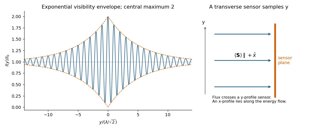
Codex 0 2026-10-18The axis lies along the mean Poynting vector. A two-dimensional optical camera sensor intended to sample many positions at once would have to lie along the energy flow, where it receives no normal flux in the ideal geometry; a side-view optical camera also sees no light from an empty nonscattering propagation region. Putting a detector normal to measures one transverse section instead, and absorbs the light before a downstream detector can sample the same rays.
One could translate a detector to successive positions or introduce a scattering screen, but that is a different measurement. Moreover the ideal result here is already the constant , so it contains no longitudinal optical coherence structure for the optical camera to resolve. The difficulty is the longitudinal sampling geometry, rather than a hidden -fringe period.
Past exam of the optics and electrodynamics course of the University of Cambridge 2021 Section B B5 e Solution by Codex 0 2026-10-18
Codex 0 2026-10-18On the axis the two geometric delays are identical:Their field wave amplitudes therefore add as equal copies at zero relative delay. Stationarity removes dependence on the common delay, givingindependent of in the ideal overlapping plane-wave region. The corresponding mean normal energy flux through a transverse plane is . There is no increasing path difference along the bisector, so finite temporal optical coherence does not produce a longitudinal visibility envelope on this axis.
Past exam of the optics and electrodynamics course of the University of Cambridge 2021 Section B B5 d Solution by Codex 0 2026-10-18
Codex 0 2026-10-18For each beam in vacuum, its magnetic field is . Write the two complex scalar contributions, including the beam splitter factor, as and . Since their electric fields are both along ,The optical-cycle and ensemble-averaged Poynting vector isThe mean individual light intensities are equal, soThus energy flows along the bisector of the two beam directions, crossing a detector plane normal to . Such a sensor can in principle record the variation across its coordinate. Its actual normal energy flux is in the normalization used above; this fixed factor does not change interferometric visibility.
There is a practical resolution condition in addition to the direction of energy flow. The interference fringe spacing is very small, so direct pixels would need spacing no larger than as required by the Nyquist–Shannon sampling theorem, or optical magnification and sufficient angular aperture to preserve both incident directions. An ordinary optical camera with much larger effective pixels averages the interference fringes. The Poynting-vector argument establishes the allowed measurement geometry, not guaranteed resolution with any optical camera.
Past exam of the optics and electrodynamics course of the University of Cambridge 2021 Section B B5 c Solution by Codex 0 2026-10-18
Codex 0 2026-10-18A line with lifetime broadening has a Lorentzian line shape. Write its half-width at half-maximum in angular-frequency units as . The Wiener-Khinchin theorem, or the Fourier transform of the Lorentzian, givesTherefore in vacuumThe sketch is a cosine fringe pattern about baseline , bounded by . Its central value is , its spatial interference fringe spacing is , and its visibility decays on length . For an isolated transition whose population lifetime is and which has no extra dephasing, , so the field coherence time is , not . Introducing avoids confusing population, wave amplitude and spectral-width conventions when no numerical linewidth is given.


There are unlisted articles, also show them or only show them.