A change of electrical resistance associated with an applied magnetic field, with material, temperature, measuring electric current and preparation specified. The response can depend on magnetic history as well as the instantaneous field. A magnetoresistance measurement therefore compares defined states, rather than treating every material as a single-valued function of field magnitude.
If one temperature-dependent relaxation scale controls a fixed carrier population and fixed orbital geometry, the magnetoresistance ratio can collapse onto a function of . This is Kohler's rule. For the equal-mobility compensated two-carrier magnetoresistance model, and . Therefore plotting against gives a common straight line of slope . A collapse tests the scaling relation; it does not by itself prove this particular microscopic carrier model. Multiple independently varying scattering times or carrier populations can spoil it.
Consider isotropic Electrons and electron holes with equal density , charges , equal positive charge carrier mobility , and single-species zero-field electrical conductivity . In a transverse magnetic field, opposite Hall conductivity components cancel, while diagonal components add to . Inverting gives and . Its large-field growth is . The total zero-field resistivity is , half the single-species resistivity; confusing these quantities introduces a factor-of-two normalization error.
Giant magnetoresistance connects the relative magnetizations of adjacent magnetic layers to their electrical transport. In a suitable magnetic-metal/nonmagnetic-metal stack, aligning the layers can leave one spin channel with an easy conducting path through both magnetic layers; opposite alignments make each channel encounter a more resistive layer. Albert Fert's account traces the spin-dependent-conduction idea to Nevill Mott and distinguishes the later device geometries.[ref]
Nobel Lecture: Origin, development, and future of spintronics by Albert Fert. pp.1517–1520, spin-dependent conduction and CIP/CPP geometry
The beauty is that a magnetic arrangement becomes an electrical readout. Preparing reproducible layers, establishing their magnetizations, and measuring electrical resistance are separate parts of that inference. The Fe-Cr giant magnetoresistance experiments show how those parts were joined; the two-current resistor model isolates a simple transport mechanism under stated assumptions.
The 1988 study grew alternating iron/chromium layers by molecular beam epitaxy on gallium arsenide. Magnetization and torque measurements tested the magnetic configuration. An AC electrical resistance measurement passed electric current along the layers while the applied magnetic field changed. Comparing field directions and spacer thicknesses linked the resistance decrease to magnetic saturation. Electron microscopy and surface analysis checked layer formation, while leaving atomic-scale interface roughness unresolved.[ref]
Giant Magnetoresistance of (001)Fe⁄(001)Cr Magnetic Superlattices by Mário Norberto Baibich and others. pp.2472–2474, preparation, Figs.1–3 and interface limits
The independent Jülich study used four-terminal sensing on epitaxial Fe/Cr/Fe strips. A single iron film supplied an anisotropic magnetoresistance comparison. Magneto-optic Kerr effect signals and Brillouin light scattering from spin waves identified the layer alignments, rather than inferring them from resistance alone. Field scans along different magnetic axes connected the optical signatures to the resistance changes.[ref]
Enhanced magnetoresistance in layered magnetic structures with antiferromagnetic interlayer exchange by G. Binasch and others. pp.4828–4830, four-point method, reference film and Figs.1–2
Peter Andreas Grünberg's retrospective explains why the preceding interlayer exchange coupling measurements mattered: coupled spin wave modes supplied signatures of magnetic alignment before that alignment became an electrical signal.[ref]
Nobel Lecture: From spin waves to giant magnetoresistance and beyond by Peter Andreas Grünberg. pp.1533–1535, coupled modes and antiferromagnetic interlayer exchange
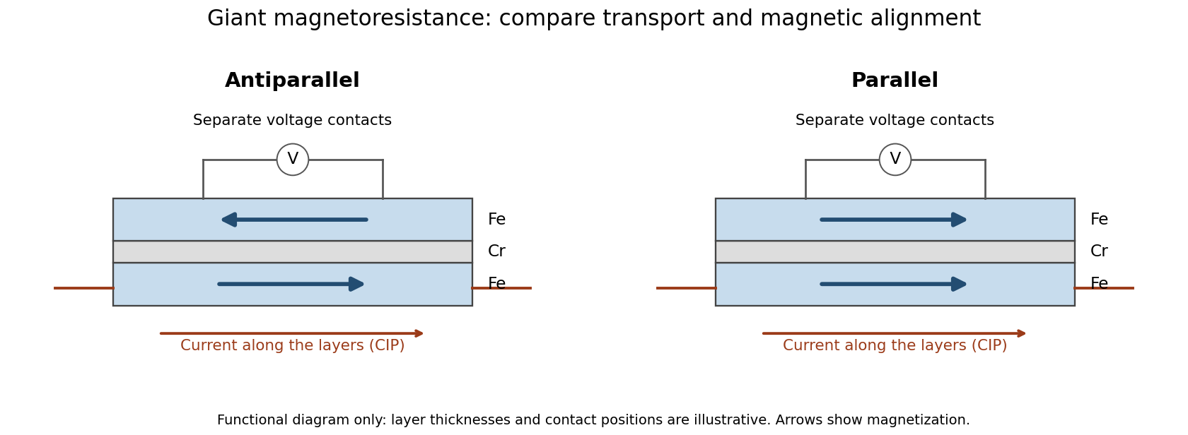
Current along a magnetic multilayer and an independent check of layer alignment
. Original functional illustration of current-in-plane transport and a generic four-terminal readout. Two idealized magnetic configurations are shown; dimensions, contact positions and layer count do not reconstruct either historical specimen. Optical probing supplies alignment information independently of the electrical signal. Source. Details.A resistance curve alone does not reveal the microscopic direction of every magnetic layer. The optical measurements add a different observable, while the reference film tests an orientation-dependent response that can occur without a multilayer. Sample preparation and cross-checks therefore belong to the physical explanation.
The measuring electric current flows along the layer planes. This is the geometry of the Fe-Cr giant magnetoresistance experiments. Scattering and current paths through an extended stack require a transport description; treating successive layers as ordinary series resistors would not follow from this geometry.
The measuring electric current crosses the layer planes. This geometry motivates the serial-layer paths in the two-current resistor model. A quantitative material calculation can also require interface electrical resistances, spin relaxation and spin accumulation; the circuit below intentionally isolates a smaller set of assumptions.
Consider two identical magnetic layers separated by a nonmagnetic layer, between reservoirs that impose the same terminal electric potential difference on both spin channels. Neglect spin-flip scattering and assume each layer obeys Ohm's law. In a magnetic layer, define positive channel electrical resistances . Let the spacer contribute to each channel. These are circuit parameters, not measured iron or chromium resistivities.
For parallel layer magnetizations, one channel meets and the other . For opposite layer magnetizations, each meets one , one , and the spacer. The two channels share the same terminal electric potential difference and run in parallel. Writing givesThe inequality is algebra, given the specified network. It shows how a difference between spin-channel responses can yield a difference between magnetic configurations even though all the constituent resistors are ohmic.
For chosen , , , the parallel channels have total electrical resistances and , while the opposite-alignment channels each have . Thus and . At a common terminal electric potential difference , the total electric currents are and , respectively.
A quoted percentage needs its denominator. Define the resistance increase relative to the low-resistance state by . The decrease relative to the high-resistance state is instead . For ,The chosen example has and : a increase and a decrease describe the same pair of resistances. A paper reporting a field-induced drop relative to its zero-field value need not be using the same percentage convention as a plot normalized by .
Define a dimensionless channel contrast and spacer ratio . Positive give , and substitution gives the displayed expression. Equal channel responses, , eliminate the model's magnetic-configuration signal. Increasing the common spacer resistance at fixed increases the denominator and decreases .
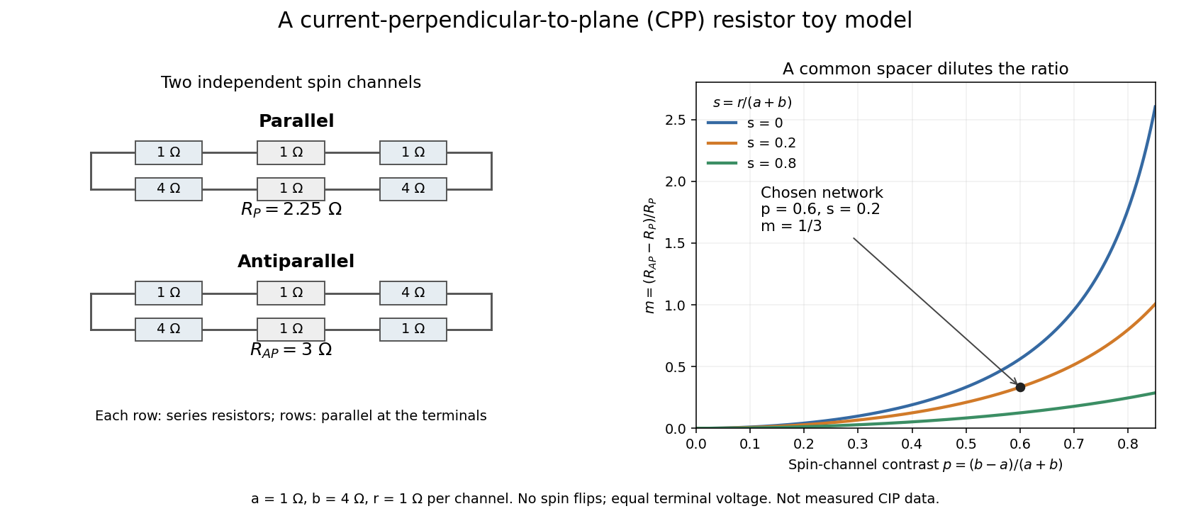
This is a controlled comparison within the model. In an actual multilayer, changing a spacer thickness can change the magnetic coupling and the interfaces as well as electrical transport. Spin-flip scattering also mixes the channels that the calculation kept independent.
Let the first layer have channel resistances and the second , with a common spacer . Define . The same circuit rules giveSubtracting their numerators gives . The sign therefore depends on whether the two layers favor the same global spin channel. With , and , the values reverse: , . The model's ratio is then . Positive magnetoresistance was a consequence of the identical-layer assumptions, not a theorem about every two-channel network.
A device with a reference magnetic layer whose magnetization is comparatively fixed and another layer whose magnetization responds more readily to an applied field. The resistance reads their relative alignment. Fert's account describes how such giant magnetoresistance sensors entered hard-disk read heads in 1997.[ref]
Nobel Lecture: Origin, development, and future of spintronics by Albert Fert. p.1519, spin-valve structure and historical read-head adoption
Articles by others on the same topic



Magnetoresistance is a phenomenon in which the electrical resistance of a material changes in the presence of a magnetic field. This effect can be observed in various types of materials, including metals, semiconductors, and insulating materials. ### Key Points about Magnetoresistance: 1. **Basic Principle**: The electrical resistance of materials typically depends on their physical and chemical properties, but when a magnetic field is applied, the movement of charge carriers (such as electrons) within the material can be affected.