Polarization of waves describes the direction and time-dependent geometry of a transverse wave's vector during its oscillation at a fixed position. In three spatial dimensions, a transverse wave can have two independent directions of oscillation, both perpendicular to its direction of propagation. For polarization of an electromagnetic wave, the relevant vector is the transverse electric field; for a mechanical transverse wave, it can be the transverse displacement. A purely longitudinal wave has no choice between these transverse directions, and the orientation of a static electric field is not polarization of waves.
Choose transverse axes in a Cartesian coordinate system. A monochromatic wave with a fixed phase difference has the real electric fieldHere are wave amplitudes, is the angular frequency, and is the phase difference of the oscillation relative to the oscillation. The vector's tip traces its path during the wave period . Both plotted coordinates are real electric field components; neither axis represents the imaginary part of a complex amplitude.
For nonzero wave amplitudes, or modulo gives linear polarization: the vector moves back and forth along a fixed line. Equal nonzero wave amplitudes and modulo give circular polarization: the tip traces a circle of constant radius. Unequal nonzero wave amplitudes with give a noncircular ellipse whose axes coincide with . More generally, nonzero wave amplitudes and give elliptical polarization, with circular polarization as a special case. If exactly one wave amplitude vanishes, the nonzero wave has linear polarization for every ; if both vanish, there is no nonzero wave to assign a polarization of waves. [ref]
https://www.feynmanlectures.caltech.edu/I_33.html#Ch33-S1. Feynman Lectures, I §33–1: the electric vector of light
.For example, take , so the wave period is . The choices , and , with electric field wave amplitudes in , produce respectively the line segment , the circle and the ellipse , when coordinates are measured in . At , their tips are respectively , and . The last two share a point without having the same path.
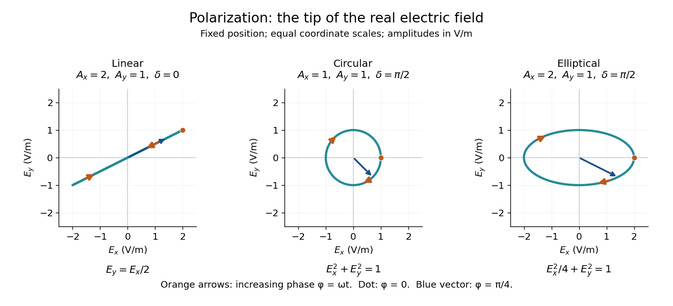
Real transverse electric field trajectories for linear polarization, circular polarization and elliptical polarization
. All panels use the same coordinate scale. Orange arrows follow increasing wave phase ; the dot marks . The blue vector is the electric field at . These are paths at one fixed position, rather than spatial drawings of a propagating wave. Details.Resolving the electric field into two transverse components makes polarization of waves useful: the same frequency and wave amplitudes can describe different paths when their phase difference changes. An ideal linear polarizer selects the component along its pass axis, letting its orientation probe the direction of linear polarization through Malus's law. A fixed pair of wave amplitudes and a fixed phase difference describe one stable path; unpolarized light requires a statistical description rather than one fixed ellipse.
Pure polarization means that the transverse components of a light field have a fixed complex amplitude ratio. A single Jones vector describes the state; its coherency matrix has rank one. Removing overall intensity and a common phase leaves two real parameters, which determine its polarization ellipse.
The degree of polarization quantifies how strongly a transverse optical field departs from an unpolarized mixture. Here are the eigenvalues of its coherency matrix. For two mutually uncorrelated orthogonal linear components of intensities , . It is undefined when the total light intensity is zero. A signed difference is a separate convention that also identifies a preferred polarization direction.
The optical coherency matrix records the second moments of transverse complex amplitudes. Normalize its trace to light intensity. Under a deterministic Jones matrix , . Unpolarized light has , so its output intensity is ; it cannot be represented by one fixed Jones vector.
Jones calculus represents fully polarized light by a Jones vector and linear optical transformations by complex matrices.
A Jones matrix is a complex two-by-two linear transformation of a Jones vector through a deterministic nondepolarizing optical element. Successive elements multiply in reverse reading order. An ideal linear polarizer along a real transverse unit vector has matrix . A common nonzero scalar phase does not change the output polarization of waves.
For fixed circular eigenvectors , let . A uniform optical medium with amplitude propagation coefficients has the displayed Jones matrix. Put and . ThenThe sum of the two modal exponentials supplies a hyperbolic cosine, not its reciprocal. The determinant is , and . Real modal coefficients give circular dichroism; purely imaginary coefficients give lossless circular birefringence. Complex modal labels do not have an intrinsic numerical ordering.
A Jones vector records the two transverse complex amplitudes of a completely polarized monochromatic wave. Multiplication by a common nonzero complex number preserves its polarization of waves, while changing overall amplitude and phase. With the convention , gives , an ellipse with the longer axis along . Handedness labels require both a viewing direction and a naming convention.
For a differentiable Jones vector with , the ratio fixes polarization independently of common amplitude and phase. The title quotient derivative tests first-order polarization sensitivity. If for a complex scalar , then . For a lossless normalized output, differentiation of makes , so this change is a common phase. A vanishing component requires the complementary ratio or a basis-independent polarization coordinate instead.
For an elliptically polarized wave, the tip of its transverse vector traces an ellipse at a fixed point during each wave period. For polarization of an electromagnetic wave, this is the electric field vector. With the real components in polarization of waves, assume and . Eliminating time givesA short derivation uses and the cosine addition formula to obtain ; squaring and using the sine and cosine identity gives the displayed equation. Outside phase quadrature, the mixed term gives a tilted ellipse; are component wave amplitudes and need not be its semi-major and semi-minor axes.
In phase quadrature, , the mixed term vanishes. For , the ellipse is , its semi-major and semi-minor axes have lengths and , and its electric field magnitude varies between and . At with , the electric field is and has magnitude . Equal wave amplitudes instead give circular polarization, a special case of elliptical polarization with constant magnitude. As approaches or , the ellipse collapses to a line segment and gives linear polarization; this limit is degenerate rather than a nondegenerate ellipse.
Changing from to reverses traversal of the same ellipse. In the displayed plot, moves from toward negative as time increases. A label such as right- or left-handed circular polarization additionally requires a stated viewing direction and naming convention: viewing along propagation and viewing against propagation reverse the apparent rotation. [ref]
https://www.feynmanlectures.caltech.edu/I_33.html#Ch33-S1. Feynman Lectures, I §33–1: polarization conventions
.The ellipse records both the relative wave amplitudes and the phase difference of two transverse oscillations. This separates a change of polarization of waves from a change of overall wave amplitude: multiplying both components by the same positive factor enlarges the ellipse while preserving its shape and orientation.
A rotating ideal linear polarizer can probe this geometry. For the ellipse in phase quadrature, orthogonal projection onto a pass axis at angle gives , in . Averaging its square over a wave period gives , while the incoming squared electric field magnitude averages to . Thus the transmitted fraction of light intensity is : it is at , at and at . There is no single incident line of linear polarization to insert into Malus's law; projecting the electric field and averaging its square is the appropriate generalization. This measurement cannot distinguish from , because reversing the traversal leaves all these squared averages unchanged.
Two coherent waves with common propagation direction and frequency can combine into a polarization ellipse. Take circular components , and add along . The resulting semiaxes are and . Choosing positive gives a nondegenerate ellipse with unequal axes. Uncorrelated relative phases do not describe the same fixed pure polarization.
The polarization ellipse is the curve traced by the transverse electric field of a monochromatic wave at a fixed point. Its orientation and signed ratio of minor to major semiaxis specify a pure polarization. A zero minor semiaxis gives linear polarization, and equal semiaxes give circular polarization.
For incident light with linear polarization, an ideal linear polarizer transmitswhere is light intensity and is the angle between the incident electric field's line of oscillation and the polarizer's pass axis. The input and output are compared in the same medium. The classical explanation is an orthogonal projection: for a unit vector along the pass axis,The dot product reduces the transmitted wave amplitude by . For a plane electromagnetic wave in the same medium, light intensity is proportional to squared electric field wave amplitude, giving Malus's law. For example, transmits one quarter of the incident light intensity, although the transmitted wave amplitude is one half. [ref].
Start with light already in linear polarization along the horizontal axis and let its light intensity be . Two ideal absorbing linear polarizers with pass axes and give . Insert a polarizer between them: the first leaves unchanged, the middle transmits with linear polarization along , and the last transmits with linear polarization along . Each angle in Malus's law is relative to the preceding output, so the final step uses :
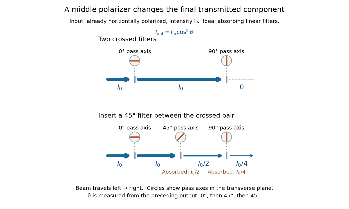
Two crossed polarizers transmit zero; inserting a middle polarizer transmits for initially horizontal linear polarization
. Pass axes are measured from horizontal. Each blue segment represents transmitted light intensity, and each inset shows the pass axis in the transverse plane. The two successive changes each halve light intensity by Malus's law. Details.For these ideal absorbing polarizers, the rejected electric field component transfers energy to the filter. In the three-filter arrangement the middle absorbs the fraction , and the last absorbs , leaving transmitted. Conservation of energy holds at each step. Inserting the middle polarizer changes the linear polarization arriving at the last one; it does not create light. The effect illustrates why successive orthogonal projections cannot generally be replaced by a single comparison of the first and last axes.
The initially horizontal assumption matters. For unpolarized light of light intensity , the first ideal linear polarizer transmits : averaging over uniformly distributed incident orientations gives . The same sequence then transmits . This extra first-stage factor does not apply to the already horizontally polarized input in the figure.
For ideal polarizers with successive transverse transmission directions , the Jones matrix is the rank-one orthogonal projection . The identity reduces the transmitted probability amplitude analogue, here the optical complex amplitude, to a product of projections. For unpolarized light, the first element transmits half the incident light intensity, giving the displayed product. For a specified incident linear polarization, replace the first half-factor with its actual projection.
Unpolarized light has no preferred transverse polarization direction in its time-averaged statistics. An ideal linear polarizer transmits half its incident light intensity: equal transverse components give the averaged projection factor . This statistical description differs from the fixed deterministic phase relation of a monochromatic wave in a pure polarization of waves state.
Articles by others on the same topic



Polarization refers to the orientation of the oscillations of a wave, particularly in the context of electromagnetic waves, such as light. In simple terms, polarization describes the direction in which the electric field vector of a light wave oscillates. Here are some key points to understand about polarization: 1. **Types of Polarization**: - **Linear Polarization**: The electric field oscillates in a single plane along the direction of wave propagation.