The Center for Marine Studies is often affiliated with academic institutions focusing on marine science, oceanography, and related research fields. Such centers typically engage in research, education, and outreach related to marine ecosystems, conservation, and the impact of human activities on the oceans. They may offer programs for students, conduct field studies, and collaborate with government and nonprofit organizations on marine conservation efforts.
The International Ocean Discovery Program (IODP) is a collaborative research initiative that aims to explore and study the Earth's oceanic systems, primarily through the drilling of the seafloor and the collection of subsurface samples. Established in 2013, IODP builds on the legacy of previous ocean drilling programs, including the Ocean Drilling Program (ODP) and the Deep Sea Drilling Project (DSDP).
The Leibniz Institute for Baltic Sea Research (Leibniz-Institut für Ostseeforschung Warnemünde, IOW) is a research institution located in Warnemünde, Germany, focused on the study of the Baltic Sea and its surrounding environments. It is part of the Leibniz Association, a network of research institutions in Germany.
The Marine Science Institute (MSI) is generally a research and educational institution focused on marine science and oceanography. Many universities and organizations have marine science institutes that conduct research, offer educational programs, and engage in outreach activities related to marine environments and ecosystems. For example: 1. **Research and Education**: Marine Science Institutes typically conduct research on various aspects of marine science, including biology, oceanography, marine ecology, and environmental science. They may also offer undergraduate and graduate programs in these fields.
The National Undersea Research Center for the North Atlantic and Great Lakes (NURC-NAGL) is an organization focused on marine research, exploration, and education in the underwater environments of the North Atlantic region and the Great Lakes. Part of a broader network supporting undersea research initiatives, it aims to advance scientific understanding of marine ecosystems, promote the responsible use of ocean resources, and enhance the study of underwater habitats.
The Oceanic Platform of the Canary Islands refers to the underwater geological structure that includes the volcanic and sedimentary deposits surrounding the Canary Islands, an archipelago located off the northwest coast of Africa. This platform represents the oceanic environment surrounding the islands and includes various features such as seamounts, ridges, and the continental slope.
The Scottish Association for Marine Science (SAMS) is a leading marine research organization based in Scotland. It is primarily focused on understanding the marine environment and its ecosystems, contributing to marine science research, teaching, and public engagement. SAMS conducts a variety of research projects related to marine biology, oceanography, marine ecology, and the impacts of climate change on marine systems.
Marine energy refers to the renewable energy derived from the ocean and its various phenomena. It encompasses a range of technologies and resources that harness the energy produced by ocean currents, waves, tides, thermal gradients, and other marine processes. The primary types of marine energy include: 1. **Wave Energy**: Energy generated from the surface motion of waves. Technologies often involve devices like oscillating water columns, point absorbers, and oscillating buoys that convert wave motion into electricity.
Ocean Thermal Energy Conversion (OTEC) is a renewable energy technology that harnesses the temperature difference between warmer surface ocean water and colder deep ocean water to generate electricity. The principle behind OTEC is based on the fact that the ocean's surface water is typically warmer than the water at greater depths. ### How OTEC Works 1.
The Fundy Basin is a significant geological depression located in the eastern part of North America, primarily extending through New Brunswick and Nova Scotia in Canada. It is named after the Bay of Fundy, which is renowned for having one of the highest tidal ranges in the world. The basin is part of the larger Atlantic Canada region and is characterized by its unique geological features, including sedimentary rock formations that offer insights into the region's geological history.
A maritime nation is a country that has a strong connection to the sea, characterized by a significant engagement in maritime activities such as shipping, fishing, trade, naval power, and maritime exploration. These nations often have coastlines, numerous ports, and a history of maritime commerce and naval operations. Key features of a maritime nation include: 1. **Geographical Location**: Typically, they have access to oceans, seas, or major waterways, which facilitates maritime trade and exploration.
RV Maurice Ewing is a research vessel operated by the Lamont-Doherty Earth Observatory (LDEO) of Columbia University. It is named after the prominent American geophysicist Maurice Ewing, known for his contributions to marine geology and geophysics. The vessel is used primarily for oceanographic research, including studies related to marine geology, ocean circulation, and environmental change.
Robert R. L. Guillard is a prominent figure in the field of oceanography and marine science, particularly known for his work on phytoplankton and oceanic ecosystems. He has made significant contributions to our understanding of marine microorganisms and their role in the ocean's biological carbon pump. Guillard is also well-known for his research on the growth and cultivation of phytoplankton in laboratory settings, which has important implications for both scientific research and environmental management.
Research vessels of China refer to a range of specialized ships operated by various Chinese institutions and government agencies for marine research and oceanographic studies. These vessels are equipped with advanced technologies and instruments to conduct scientific research in fields such as marine biology, oceanography, geology, climatology, and environmental monitoring.
Research vessels of Germany are specialized ships used for scientific research in marine and oceanographic studies. These vessels are equipped with advanced technology and instruments to conduct a wide range of research activities, including but not limited to: 1. **Marine Biology**: Studying marine ecosystems, biodiversity, and species interactions. 2. **Physical Oceanography**: Investigating ocean currents, temperature, and salinity profiles.
Research vessels of the Netherlands are specialized ships used for scientific research, primarily in marine and oceanographic studies. These vessels are equipped with advanced technology and instruments to facilitate various types of research, including marine biology, oceanography, geology, and environmental monitoring. The Netherlands has a strong focus on maritime research due to its extensive coastline and significant maritime activities.
EUREX is a European derivatives exchange where a wide variety of financial instruments are traded, including futures and options on various underlying assets such as stocks, indices, interest rates, and commodities. It is one of the largest derivatives exchanges in the world and operates as a fully electronic trading platform. EUREX was founded in 1998 and has since become a key player in the European financial markets. It is known for its advanced trading technology, liquidity, and a broad range of products.
Nepotism is the practice of favoring relatives or close friends when it comes to positions of power, employment, or other opportunities, often disregarding merit or qualifications. This can occur in various contexts, including politics, business, and entertainment, and can result in perceptions of unfairness, reduced morale among employees, and potential abuses of power. Nepotism can undermine organizational integrity and hinder diversity, as it often excludes qualified individuals who do not have personal connections within the institution.
The **Alpha Crucis** is a research vessel owned and operated by the Australian Antarctic Division (AAD). It is primarily used for scientific research and support operations in Australia’s Antarctic and sub-Antarctic waters. The vessel is equipped to conduct various types of marine research, including oceanographic studies, environmental monitoring, and biodiversity assessments. The Alpha Crucis is often involved in logistical support for scientific expeditions, which may include transporting researchers, equipment, and supplies to remote locations.
"Pendulums" can refer to a variety of concepts depending on the context: 1. **Physics**: A pendulum is a weight suspended from a pivot point that can swing back and forth under the influence of gravity. The classic example is a simple pendulum, which consists of a mass (bob) attached to a string or rod. When displaced from its equilibrium position and released, it swings in a periodic motion.
Pinned article: Introduction to the OurBigBook Project
Welcome to the OurBigBook Project! Our goal is to create the perfect publishing platform for STEM subjects, and get university-level students to write the best free STEM tutorials ever.
Everyone is welcome to create an account and play with the site: ourbigbook.com/go/register. We belive that students themselves can write amazing tutorials, but teachers are welcome too. You can write about anything you want, it doesn't have to be STEM or even educational. Silly test content is very welcome and you won't be penalized in any way. Just keep it legal!
Intro to OurBigBook
. Source. We have two killer features:
- topics: topics group articles by different users with the same title, e.g. here is the topic for the "Fundamental Theorem of Calculus" ourbigbook.com/go/topic/fundamental-theorem-of-calculusArticles of different users are sorted by upvote within each article page. This feature is a bit like:
- a Wikipedia where each user can have their own version of each article
- a Q&A website like Stack Overflow, where multiple people can give their views on a given topic, and the best ones are sorted by upvote. Except you don't need to wait for someone to ask first, and any topic goes, no matter how narrow or broad
This feature makes it possible for readers to find better explanations of any topic created by other writers. And it allows writers to create an explanation in a place that readers might actually find it.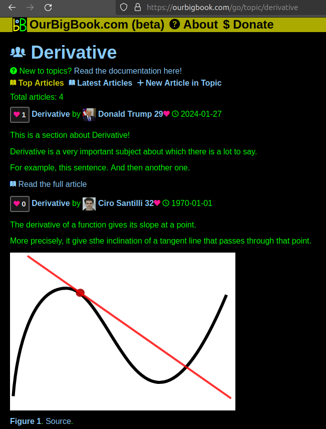
Figure 1. Screenshot of the "Derivative" topic page. View it live at: ourbigbook.com/go/topic/derivativeVideo 2. OurBigBook Web topics demo. Source. - local editing: you can store all your personal knowledge base content locally in a plaintext markup format that can be edited locally and published either:This way you can be sure that even if OurBigBook.com were to go down one day (which we have no plans to do as it is quite cheap to host!), your content will still be perfectly readable as a static site.
- to OurBigBook.com to get awesome multi-user features like topics and likes
- as HTML files to a static website, which you can host yourself for free on many external providers like GitHub Pages, and remain in full control
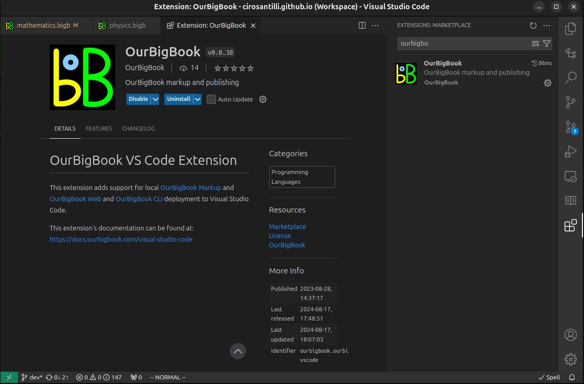
Figure 3. Visual Studio Code extension installation.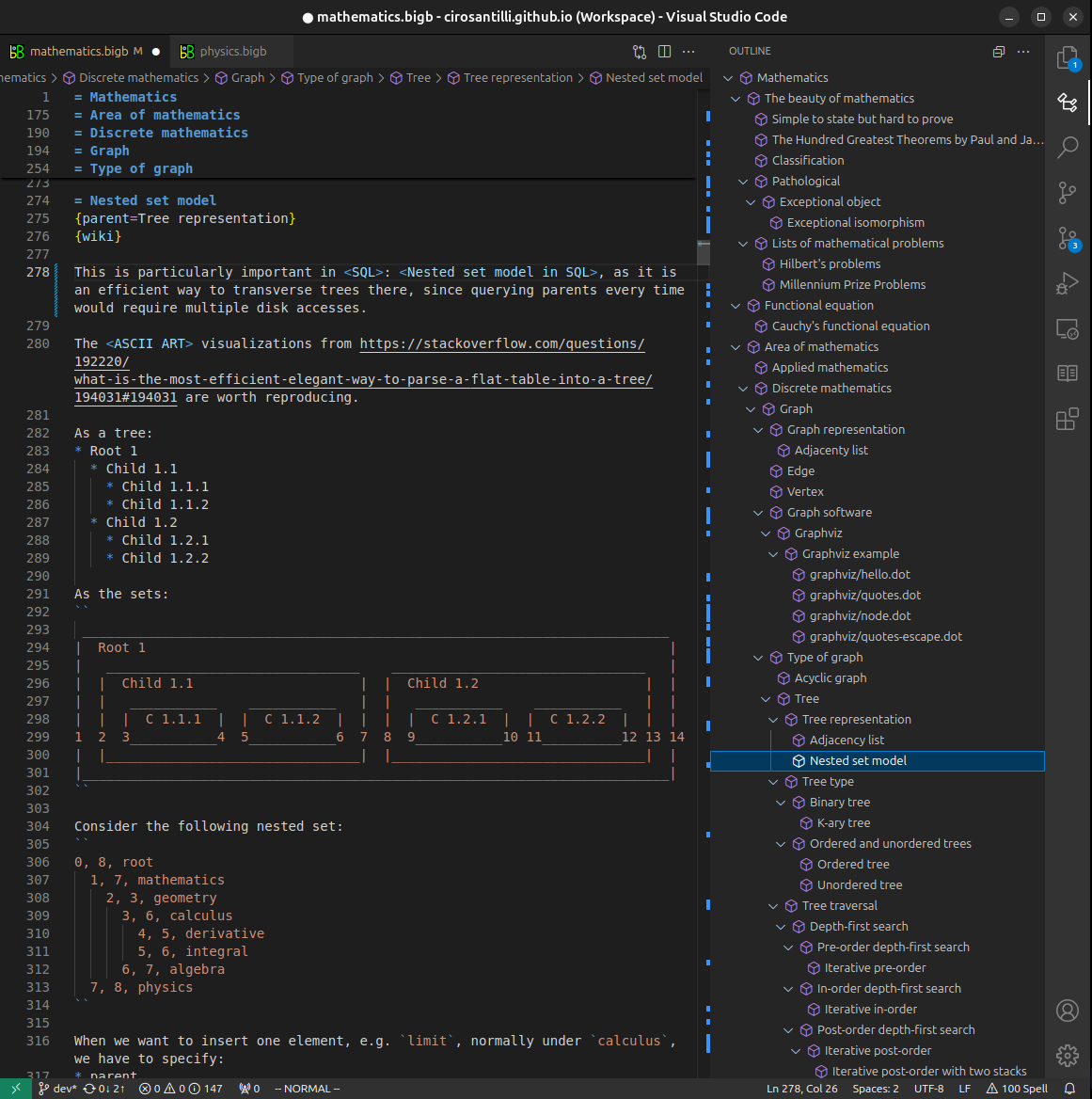
Figure 4. Visual Studio Code extension tree navigation.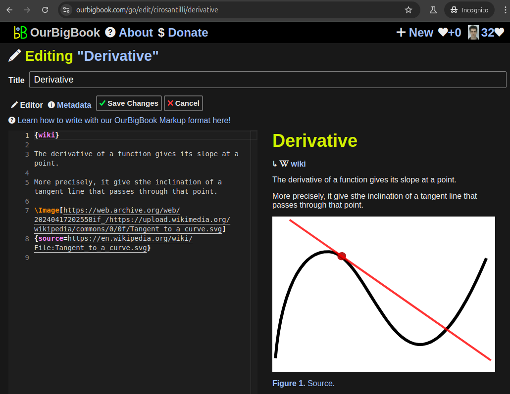
Figure 5. Web editor. You can also edit articles on the Web editor without installing anything locally.Video 3. Edit locally and publish demo. Source. This shows editing OurBigBook Markup and publishing it using the Visual Studio Code extension.Video 4. OurBigBook Visual Studio Code extension editing and navigation demo. Source. 
- Infinitely deep tables of contents:

All our software is open source and hosted at: github.com/ourbigbook/ourbigbook
Further documentation can be found at: docs.ourbigbook.com
Feel free to reach our to us for any help or suggestions: docs.ourbigbook.com/#contact