
Spin-valve read-head noise limits the field-to-electrical response: sensitivity is a response relative to noise, not merely a large total resistance. A small free-layer volume gives larger thermally driven angular fluctuations and can lose magnetic stability when its anisotropy barrier is insufficient compared with . Edge damage, stray coupling to the reference layer, nonuniform domains and Barkhausen jumps cause hysteresis and noise. Johnson noise and low-frequency resistance noise compete with a limited GMR signal; raising sense current is restricted by heating and current-induced disturbance.
One useful design combines a single-domain, gently biased free layer with a flux-compensated synthetic-antiferromagnetic reference. This reduces reference stray fields, suppresses unstable domain switching and holds the free layer near a linear operating point. The active sensing width can remain small while magnetic and electrical design preserve adequate stability and signal. An alternative is a magnetic tunnel junction with an optimized barrier, giving a larger magnetoresistance signal; its resistance-area product, shot noise and barrier reliability still require optimization. Shrinking every magnetic dimension indefinitely is not a sensitivity improvement.
[ref]
Giant room-temperature magnetoresistance in Fe-MgO-Fe junctions by Shinji Yuasa and others. Demonstration of large tunnel magnetoresistance with a crystalline MgO barrier
For collinear saturated layers, , where . Thus parallel states have and , whereas antiparallel states have and . The free layer switches in the smaller-field interval; the reference layer switches only at larger fields and its loop is shifted by exchange bias.
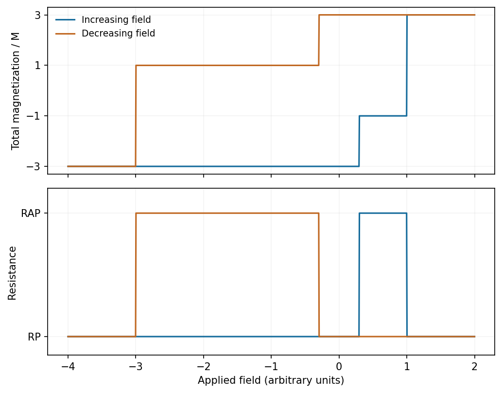
Illustrative major magnetization and resistance loops, with an exchange-shifted reference-layer reversal
. Source. Details. 
A spin valve contains a magnetically soft free ferromagnet, a thin nonmagnetic metallic spacer and a reference ferromagnet pinned by exchange bias from an antiferromagnet. The recording track's stray field rotates or reverses the free-layer moment while the reference remains approximately fixed. Spin-dependent scattering makes the resistance lower for parallel moments and higher for antiparallel moments. A sense current converts this into a voltage signal, or a fixed voltage into a current signal.
A useful angular approximation is . Biasing the equilibrium moments near gives an approximately linear response to small track fields. Pinning stability, magnetic shielding and the sensor's spatial extent matter for reading adjacent narrow bits.[ref]
The wave function vanishes in regions I and III. In region II it is sinusoidal and satisfies . The time-independent equation there isA nonzero stationary state therefore has standing-wave nodes at the two walls; it cannot have a nonzero constant ground-state wave function.
A physical bound-state wave function must be single-valued, finite, square-integrable and normalizable. Across a finite step in a regular potential, both and its first derivative are continuous when the particle mass is the same on either side; integrate the Schrödinger equation across an infinitesimal interval to obtain the derivative condition. The second derivative need not be continuous.
An infinite hard wall is an exception to derivative matching: the interior wave function vanishes at the boundary, but its derivative need not equal the exterior zero derivative. A delta-function potential also permits a prescribed derivative jump, and an effective-mass interface requires the appropriate mass-weighted matching condition. Thus ordinary finite-step conditions should not be asserted without qualification for every singular potential.
Place the Ag particles near the emitting shell, along the outer sidewalls or accessible shell at the base. Its emission is close to the localized surface plasmon resonance; the core emission is more detuned and farther from an externally placed particle. The plasmon near field decays with distance, so the local emitter-field overlap matters as well as spectral overlap. A thin spacer can reduce direct-contact nonradiative quenching.
The emission energies are approximatelyDraw the Al-rich interface as a wider-gap barrier between these two emitting regions: a raised conduction-band edge impedes electron transfer, and a lowered valence-band edge impedes hole transfer. The following is a consistent straddling-barrier schematic, with the shell having the smaller optical gap.
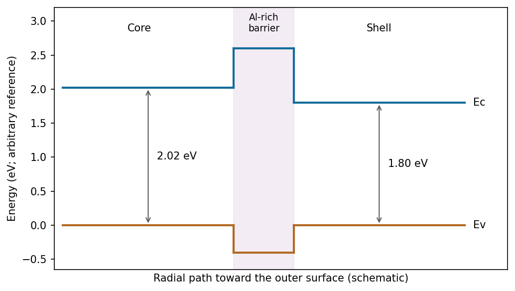
One consistent core–Al-rich-interface–shell alignment; absolute offsets are not fixed by the emission wavelengths
. Source. Details. 
The two emission wavelengths determine optical transition energies, not unique conduction- and valence-band offsets. Exciton binding, confinement and strain can shift emission relative to the bulk band gap. The stated barrier supports inhibited charge exchange; its separate electron and hole barrier heights need additional band-alignment data.
In selective-area epitaxy, precursors supplied by metal-organic vapour-phase epitaxy incorporate on exposed crystalline InP through patterned openings in a silicon-nitride mask. Epitaxial facet-dependent incorporation and surface diffusion select axial and radial growth rates. Advantages include lithographic position and pitch control, an epitaxial orientation relationship and the absence of a foreign metal catalyst. Limitations include mask patterning, selective nucleation requirements, facet-dependent composition, loading and pitch effects, and unwanted radial growth.
In vapour-liquid-solid growth, precursors decompose and supply material to a liquid catalyst droplet; supersaturation drives precipitation at the liquid-solid interface. Droplet size can control wire diameter and enable high aspect ratios. Limitations include possible catalyst contamination, droplet stability and coarsening, composition memory at heterointerfaces, and restrictions from the catalyst phase diagram. Patterned catalyst placement can also control position, so positional ordering is not exclusive to selective-area growth. Conversely, selective-area wires are not automatically free of taper or compositional interfaces.[ref]
Efficient Green Emission from Wurtzite AlInP Nanowires by L. Gagliano and others. Selective-area growth and composition-dependent nanowire structure
There are unlisted articles, also show them or only show them.