
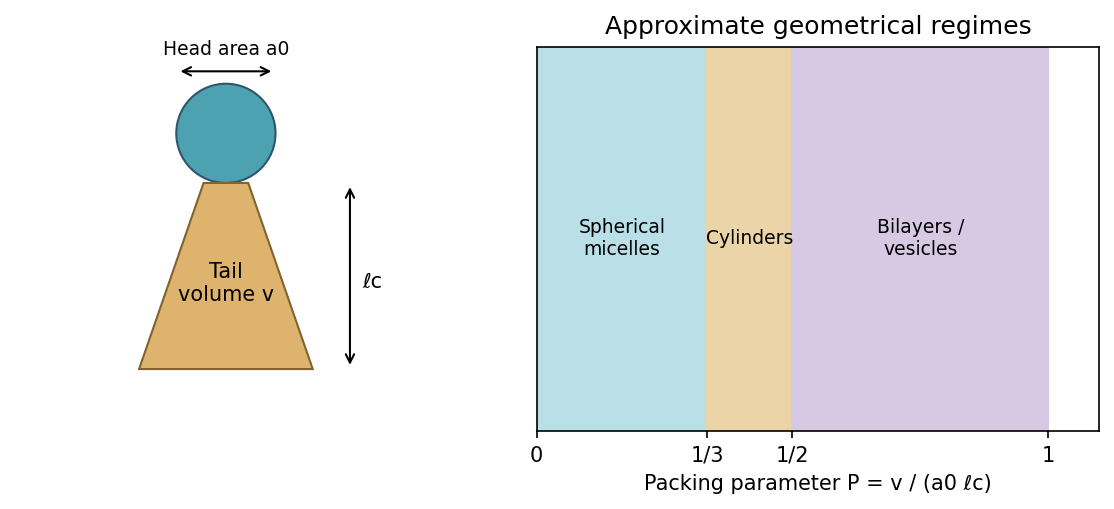
For ideal spherical micelles, and , giving . For a long cylindrical micelle, , so cylinders can accommodate larger packing parameters while keeping : roughly favours cylinders. Relatively small head area or greater tail volume reduces positive curvature.
For a planar bilayer leaflet of hydrophobic thickness , , with . Thus favours bilayer/vesicle structures, with nearly planar bilayers toward . The two leaflets put hydrophobic tails together and hydrophilic heads toward water. For , inverse structures become possible. These bounds are approximate packing guides; chain stretching, head interactions and aggregate free energy determine actual phase boundaries.
[ref]
Theory of self-assembly of hydrocarbon amphiphiles by Jacob N. Israelachvili and others. General micelle/bilayer geometrical packing model
An amphiphile has a solvent-compatible polar head and a hydrophobic tail region. The three geometrical parameters are the tail volume , effective head-group area at the interface, and maximum effective tail length . Their dimensionless combination is the amphiphile packing parameter, .
With ballistic conductance quantization, as a gate opens the channel, conductance plateaux at appear; successive transverse modes add one quantum, approximately per spin-degenerate subband. Their appearance is the key low-temperature electrical signature.
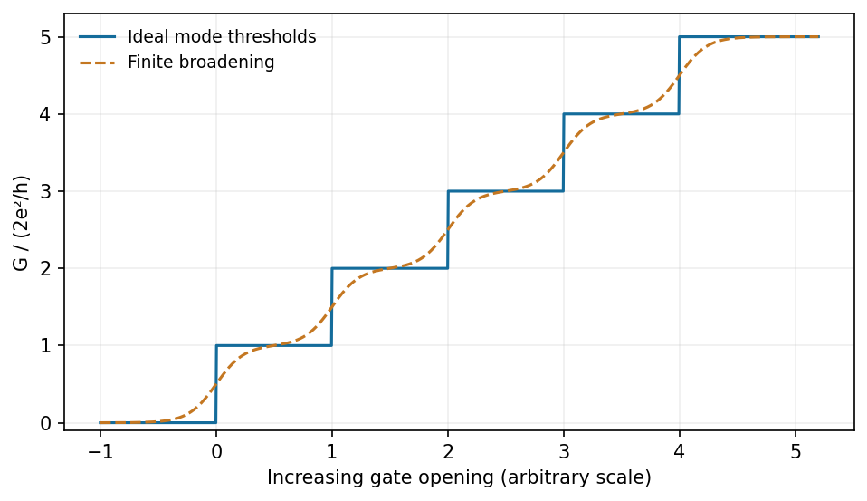
Ideal conductance plateaux sharpen as thermal and disorder broadening become small compared with subband spacing
. Source. Details. Require transverse confinement with separated subbands, and measurement-bias energy well below the subband spacing, a mean free path exceeding the channel length, and smooth low-reflection coupling to reservoirs. Correct for appreciable external series resistance. Phase coherence is needed for additional interference oscillations, but perfect phase coherence across an entire macroscopic circuit is not a separate requirement for the basic mode-counting result. A field that resolves spin splitting can produce increments.[ref]
Quantized conductance of point contacts by B. J. van Wees and others. Gate-controlled ballistic GaAs-AlGaAs point contacts and conductance steps
A larger-gap AlGaAs barrier has a higher conduction-band edge than GaAs. Donors in AlGaAs supply electrons that transfer into lower-energy GaAs states, leaving a positively charged donor region. The resulting electrostatic field bends the GaAs conduction band into a triangular interface well. Motion normal to the interface is quantized, while motion parallel to it remains approximately free, producing a two-dimensional electron gas.
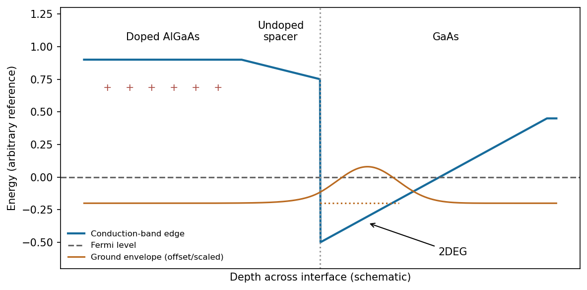
An illustrative remotely doped heterojunction separates the electron envelope from ionized donors
. Source. Details. The confined envelope peaks just inside GaAs and decays into the AlGaAs barrier; a triangular-well treatment gives an Airy-function-like envelope with boundary matching. An undoped spacer separates the electrons from the donors, strongly reducing ionized-impurity scattering compared with uniformly doped 3D material and enabling high mobility. Band offsets, donor supply, interface roughness and electrostatics jointly determine whether a single occupied subband is obtained.
n-type doping adds donor impurities with weakly bound electrons near the conduction-band edge; ionization supplies conduction electrons and leaves positive donor ions. p-type doping introduces acceptors near the valence-band edge, producing holes and negatively charged ionized acceptors. Silicon and germanium commonly use group-V donors and group-III acceptors; dopant behaviour in a compound semiconductor depends on its lattice site.
Doping sets carrier concentration, Fermi level and resistivity. Spatially patterned donor and acceptor regions form p-n junctions, transistor source/drain regions and electrical contacts; remote doping can supply carriers to a cleaner conducting layer. Compensation and incomplete ionization mean carrier density need not equal the total impurity concentration.
For parabolic bands, the density of states near a subband edge scales as , , and . Thus a quasi-1D wire has inverse-square-root singularities at successive transverse subband thresholds, a quasi-2D well has a staircase, and a bulk 3D band rises smoothly from zero. Each expression vanishes below its threshold.
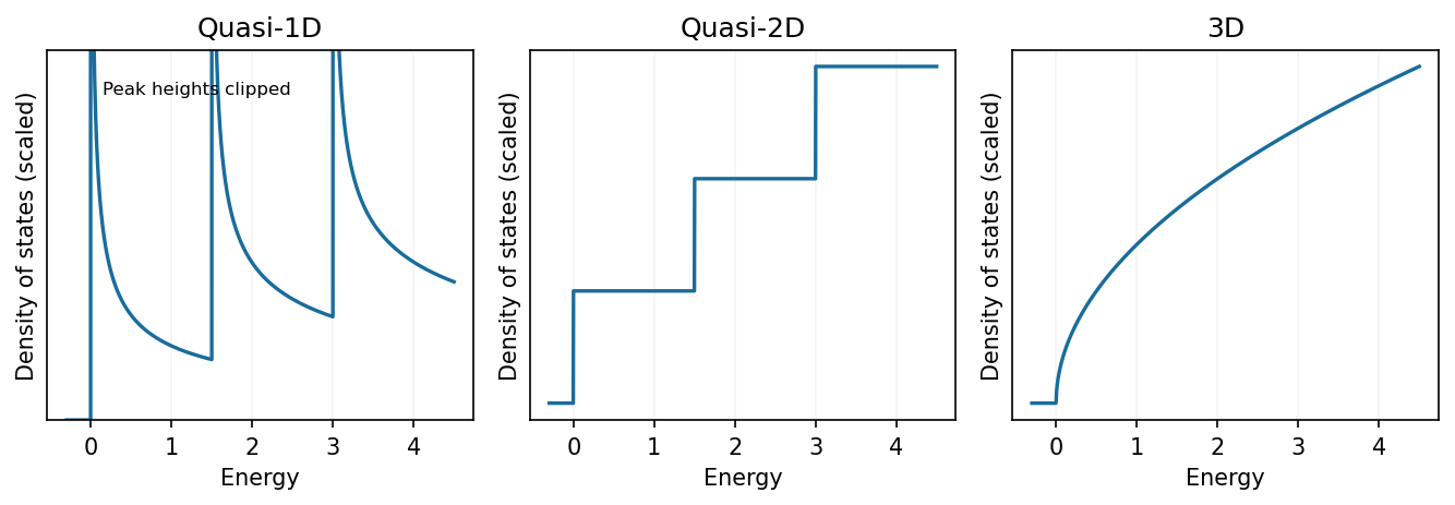
Parabolic-band density of states in one, two and three unconfined dimensions
. Source. Details. These sketches assume extended noninteracting states with simple quadratic dispersion. Finite temperature, disorder and finite lifetime broaden measured threshold features; the ideal singularity is integrable and does not represent infinitely many states in a finite energy interval.
Let the graphene lattice constant be , and choose direct primitive vectors and . Reciprocal primitive vectors satisfying areThe first Brillouin zone is a hexagon. Its corners K and K' are inequivalent valleys; M denotes an edge midpoint. In the nearest-neighbour model, , where and are the three bond vectors. The band separation is : it vanishes at K/K' and is at M, varying continuously along each edge.
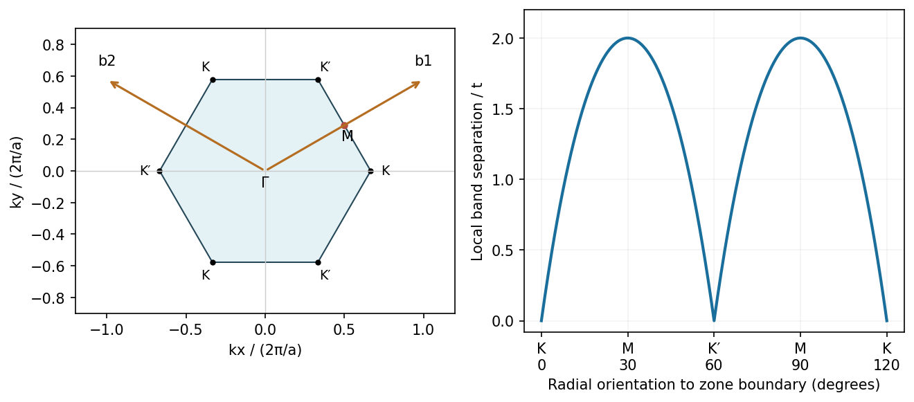
Graphene reciprocal primitive vectors and the orientation-dependent band separation on its zone boundary
. Source. Details. This graphene zone-boundary band separation is a local conduction-to-valence separation. Ideal graphene itself remains globally gapless because the bands touch at the corners. Circumferential quantization in a nanotube selects lines through this two-dimensional band structure; whether they pass through a valley determines the ideal metallic versus semiconducting distinction.
A carbon-containing feed adsorbs and decomposes on a catalytic metal particle, releasing mobile carbon. Carbon can migrate over the surface and/or through the particle, depending on catalyst, temperature and feedstock. Supersaturation and graphitic nucleation generate a curved cap; nonhexagonal rings provide the curvature needed to close its end. Continued carbon incorporation at the cap rim lifts or extends the cap into a tube while leaving a growth interface at the catalyst.
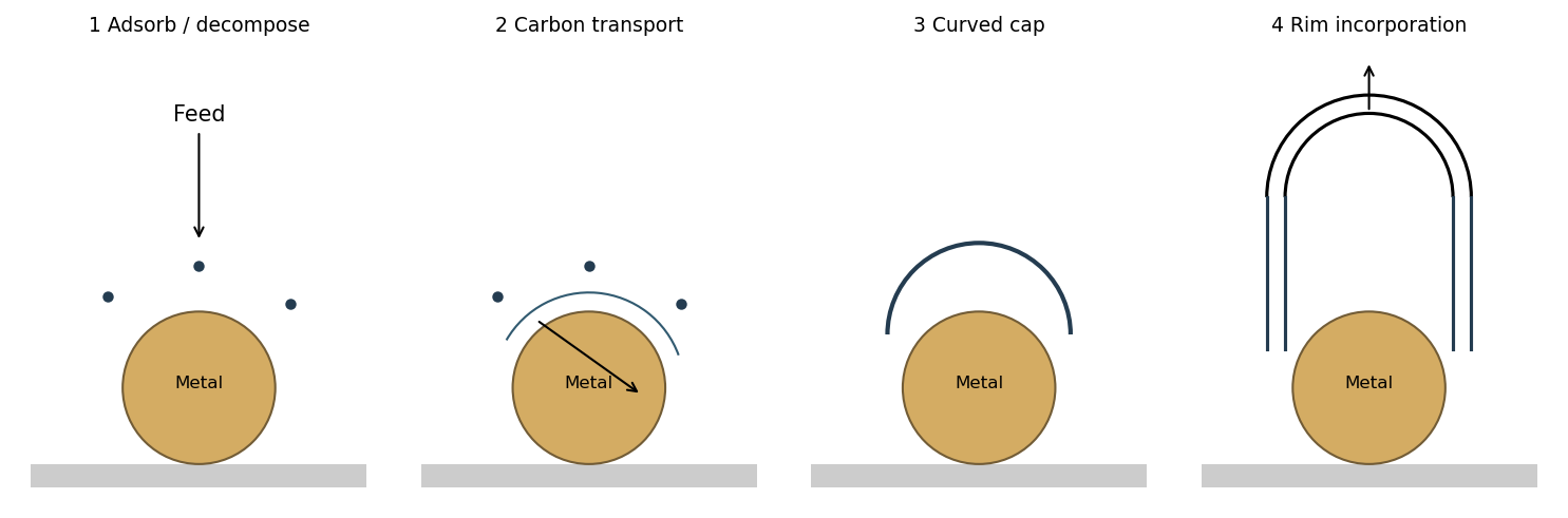
With strong catalyst-support adhesion the particle remains at the base; with weaker adhesion it can lift with the growing tube. Several shells can nucleate and extend to form a multiwall tube. Continued growth requires access to active catalyst sites: encapsulation by an impermeable carbon coating can terminate it. The catalyst need not be liquid in every chemical vapour deposition growth mechanism, and bulk dissolution is not the only possible carbon-transport route.
For a graphene honeycomb with C-C bond length , a primitive cell has two atoms and area . Its areal atomic density isFor the nanotube atom-count estimate, treat each shell as a graphene cylinder. The atoms per axial length areUsing the fringe spacing as an internal ruler gives representative estimates , and , consistent with radial spacings of . ThenThe meaningful estimate is of order atoms per nm, not an exact count. It assumes nearly complete cylindrical shells, uses projected dimensions in a reasonably straight segment, and neglects defects, corrugation and extra external carbon. Image uncertainty in wall count and diameter changes the estimate by tens of percent; no external scale bar is available in this figure.
This is a multi-walled carbon nanotube with a hollow interior and approximately concentric graphitic shells running along its axis. The walls show many resolved (002) fringes: a relatively straight section supports an approximate count of 16 shells, with some uncertainty from contrast and overlapping/terminated fringes. The tube is not a uniform straight cylinder: the inner channel narrows and changes direction, walls kink and curve, and some inner fringes terminate or join a partly closed internal region. The rough outer boundary contains disordered carbon or incomplete outer layers. The high-contrast material below the tube should not simply be counted as additional concentric shells.
Bending, incomplete walls and changes of atomic bonding scatter charge carriers and can mix shells, reducing the mean free path and causing extra resistance or localization. Covalent intershell links can also increase transfer between shells. Nonhexagonal rings or vacancies are plausible atomic causes, but this image does not resolve a unique ring inventory or prove a specific Stone-Wales defect. Different shell chiralities can intrinsically give different metallic or semiconducting behaviour; a (002) image alone does not assign those chiralities.
For the hydraulic ladder network, using the frontier star just defined, start at a single groove with . Put , and . The exact update isAfter all grooves have been included, the left frontier is a blind end, so no external flow passes through . The inlet-to-outlet resistance is . Iterate 49 times to obtain .
An equivalent closed form, for , isThus substitute ; no single number follows without . Checks are , , and as . The formula counts only the inter-groove segments in each rail; extra inlet/outlet lead resistances, if present, must be added separately. All elements obey linear laminar-flow pressure-drop laws.
For a triangular resistance network with edge resistances , replacing it by a star gives the arm at each terminal as the product of its two adjacent triangle resistances divided by . This Delta-star transformation preserves the pressure-flow relation at all three terminals, just as in a linear electrical network.
Apply it recursively to the two-rail ladder. Represent the first grooves by a three-terminal star with arms leading respectively to the fixed inlet, frontier of the left rail and frontier of the right rail. Grooves are added from inlet toward outlet. Adding the next pair of rail segments gives and ; the new groove closes a triangle between the old star centre and the two new rail endpoints. Convert that triangle to a star and combine its centre arm in series with .
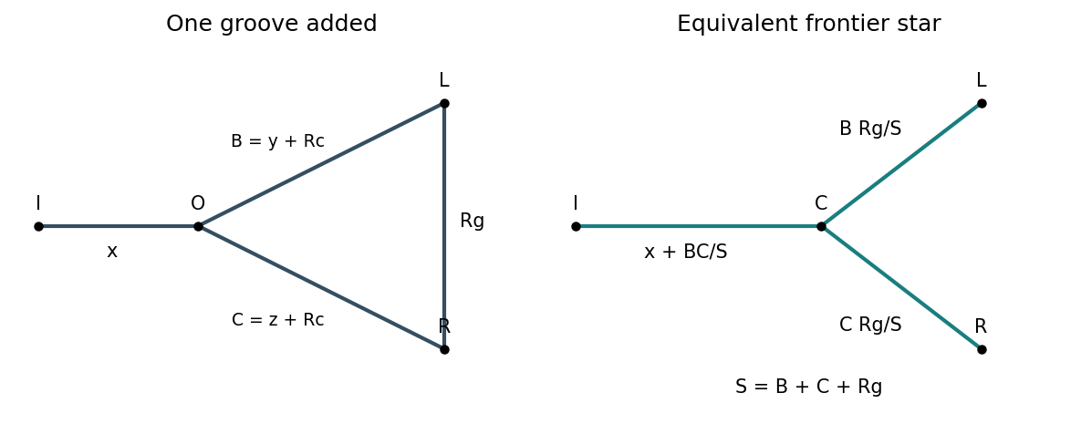


This method retains unequal pressure drops and unequal flow division along the rails; their finite resistances cannot be ignored when assigning the groove flows.
Negligible rail resistance makes all left-hand groove ends equipotential and all right-hand ends equipotential. The equal hydraulic resistances therefore connect in parallel:Here uses the total inlet flow. The two blind rail ends carry no flow beyond their final grooves.
There are unlisted articles, also show them or only show them.