Michael Faraday's induction ring separates two questions: can one electrical circuit affect another without an electrical connection, and does that effect continue under steady conditions? The surviving apparatus uses insulated copper windings around an iron ring; the Royal Institution dates the successful experiment to 29 August 1831.[ref]
Michael Faraday's ring-coil apparatus by Royal Institution. Collection record, date, materials and Description
Faraday connected one winding group to a battery, the other to a galvanometer. Making battery contact deflected the needle; maintaining contact let it return to rest; breaking contact reversed the response. Reversing the battery reversed the deflections. His separate cylinder comparison enhanced induction with iron, whereas replacing it with copper gave no enhancement over the windings alone.[ref]
Experimental Researches in Electricity, Volume 1 by Michael Faraday. First Series, §§27–30, ring, connections and reversal; §§34–35, distinct cylinder comparison
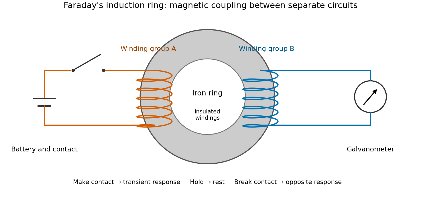

The contrast between a switching response and a quiet steady state makes mutual induction tangible. A steady primary electric current can maintain magnetic flux without sustaining a secondary electromotive force. Changes in magnetic flux linkage matter, as expressed by Faraday's law of induction. This is why a driven electrical transformer uses repeated changes in magnetic flux to supply secondary power.
The galvanometer readout of an induction pulse also separates the measured motion from the inferred electric current. Its moment of inertia and damping mean that a deflection is not an instantaneous trace of electric current. The following coupled RL induction model calculates currents in a stipulated circuit, rather than fitting Faraday's needle motion or reconstructing his switching times.
Take two electrical circuits containing coupled inductors. Let their constant self-inductances be , mutual inductance , and positive electrical resistances . Choose current directions so that the off-diagonal entries of the inductance matrix are . Assume a linear, quasistatic model, with no capacitive effects or core hysteresis. The magnetic flux linkages are and . Combining their time derivatives with resistive electric potential differences givesThe secondary is a closed, undriven electrical circuit. Require , making a positive-definite matrix. The chosen current convention fixes the signs; reversing the secondary's reference direction changes the sign assigned to and without changing the physical circuit.
There is an essential switching assumption: the primary loop remains closed when becomes zero. An ideal voltage source then imposes zero electric potential difference, allowing the current to decay. Literally opening an inductive circuit requires additional physics to determine the interruption, including possible capacitance and an electric arc. This closed-return model explains transient induction while keeping that distinction from Faraday's historical making and breaking of contact explicit.
For an exactly soluble example, set , , and . Start with zero electric currents, and apply a constant electric potential difference at . The sums and obey separate first-order linear differential equations:Their time constants are and . Thus, for ,Since , for , but as . The primary approaches . The secondary response opposes the rise of linked magnetic flux, in accordance with Lenz's law. Removing mutual inductance by setting makes the two exponentials equal and gives zero secondary electric current.
For stipulated , , and , the two time constants are and . Setting gives its largest negative magnitude atThe continuing primary electric current eventually reaches while the secondary returns to zero. These numbers belong to the stated model, not the 1831 apparatus.
Apply for and then set the drive to zero while retaining the closed primary return. By superposition, each pulse-response electric current is its equal-loop RL induction step response at minus that response at , with the step response defined as zero before its onset. All currents remain continuous at ; the drive changes their derivatives.
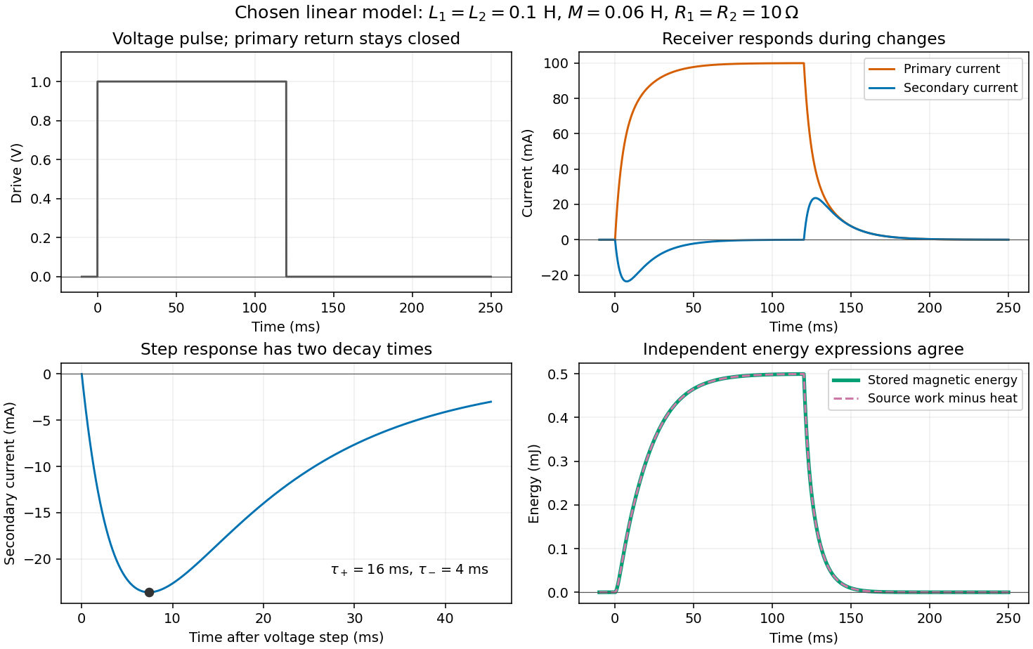

For the displayed pulse, the secondary responds negatively as the primary builds and positively as it decays. Between these transients, the primary is almost steady and the secondary is almost quiet. The energy balance of coupled RL circuits accounts for the entire process, including the energy remaining in the magnetic field when the drive changes.
The magnetic energy of this constant-inductance model isThe positive-definite matrix condition makes . Multiplying the two circuit equations by and , then adding, gives the displayed conservation of energy statement: input power supplies stored magnetic energy and Joule heating. With zero drive, . After the drive becomes zero, the stored magnetic energy supplies the remaining Joule heating.
Articles by others on the same topic
There are currently no matching articles.