More precisely, the Mach number is the dimensionless quantitywhere is the magnitude of the body's relative velocity through the surrounding gas, and is the local sound speed measured in the gas rest reference frame. For a fluid flow past a stationary body, the same Mach number uses the local fluid speed in the body's rest reference frame. A Mach number below, equal to, or above one means subsonic flow, sonic flow, or supersonic flow, respectively. The denominator is a property of the local gas: its sound speed depends on temperature and composition.[ref]
Mach Number (NASA Glenn Research Center). Mach Number, paragraphs defining the speed ratio and dependence on gas type and temperature; flight-regime list
The relative velocity matters even when the body is at rest in a wind tunnel. A uniform change of reference frame subtracts the same velocity from body and gas, so their relative velocity and the Mach number stay unchanged under a Galilean transformation. Ground speed alone cannot supply when there is wind. For an original collinear example, a body moving at over the ground through gas moving in the same direction at has . With a stipulated sound speed , its Mach number is , rather than . A moving observer changes apparent acoustic wave arrival times, as in the radial Mach number, without changing the body's Mach number relative to the gas.
Why is the threshold one so useful? Acoustic waves carry small pressure disturbances at the sound speed. In subsonic flow, such information can travel upstream relative to the body; in a uniform supersonic flow, it is swept downstream. The Mach cone turns this difference in communication into visible geometry. Matching Mach number between a wind tunnel and flight is therefore essential to matching compressible flow effects.[ref]
Mach Number (NASA Glenn Research Center). Mach Number, paragraphs on downstream propagation and matching wind-tunnel and flight Mach numbers
An actual supersonic wind tunnel experiment makes the distinction between wavefronts and shock waves concrete. In NASA Glenn's 1-by-1-foot wind tunnel, interchangeable converging-diverging nozzle blocks set the Mach number. A strut-mounted exhaust-nozzle model had a nosecone, an air plenum and transparent sidewalls for schlieren photography. Before installing the model, the researchers photographed the empty test section: two shock wave patterns originated at a wall joint after the nozzle block. This control guided model placement to keep reflected shock waves away from the plume-study region. The rig included internal total pressure and static pressure sensing and a traversing external static pressure probe. A baseline nozzle and previous pressure data supplied a planned validation comparison; the report distinguishes this plan from the observed empty-tunnel control. This establishes an apparatus origin for those visible shock waves, not a measurement of the Mach cone from an infinitesimal source. The reported finite shock wave angle cannot simply be inserted into the Mach angle formula to calibrate : shock wave strength and geometry also matter.[ref]
Wind Tunnel Model Design for the Study of Plume Effects on Sonic Boom for Isolated Exhaust Nozzles by Raymond S. Castner. Wind Tunnel Model Design for the Study of Plume Effects on Sonic Boom for Isolated Exhaust Nozzles, NASA/TM-2010-216259, §II printed p. 2; §§IV–V printed pp. 8–9; Figs. 7–10 and concluding remarks printed p. 10
In conventional schlieren photography, a bright slit source and two concave mirrors send parallel light rays through the wind tunnel and focus them at a knife edge before an optical camera. Spatial changes in mass density cause refraction; the knife edge converts the deflection into image contrast, making shock waves visible. This is the general optical principle, rather than a specification of every component in the preceding rig. A photograph projects a three-dimensional fluid flow into two dimensions; contrast alone does not provide a calibrated pressure jump or acoustic wave amplitude.[ref]
Schlieren Flow Visualization (NASA Glenn Research Center). Schlieren Flow Visualization, paragraphs describing the two-mirror slit-source and knife-edge system, density-gradient contrast, and two-dimensional recording of three-dimensional shocks
Take a steady moving point source in uniform resting gas, with constant sound speed and source velocity . Place the source at the origin at the current time . In the linear acoustics model, an emission at an earlier time has a spherical wavefront centered at with radius . An axial cross-section is the circle in the displayed equation. It is centered at the old release position, not the source's present position. The circles describe the geometry of weak acoustic waves, not a measured shock wave or its pressure jump.
For , every old circle contains the present source because its center is from the origin while its radius is the larger distance . It reaches ahead of the source. For , the rightmost point of every old circle is : the source outruns all of its old wavefronts. The continuously emitted wavefronts have a common geometric envelope, the Mach cone. The plotted discrete release times sample this continuous family; rotating the axial section about the motion axis recovers the three-dimensional construction.
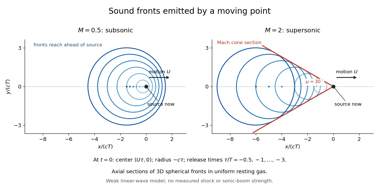
Subsonic and supersonic acoustic wavefronts from a moving point
. Original axial cross-sections at for Mach numbers and . With an arbitrary positive time scale , the sampled release times are . Each circle has center and radius ; red lines give the Mach cone section. This weak linear acoustics model predicts geometry, not measured shock wave or sonic boom strength. Details.
The radial Mach number is the source velocity projected toward the observer, divided by the sound speed. It enters the moving-surface retarded Jacobian through . The sign is directional: a source moving toward the observer has positive and compressed arrival times.
For uniform gas moving at past a resting body, an upstream-directed acoustic wave has body-frame velocity . When , this velocity points upstream. This is why the body can influence the upstream fluid flow through small pressure disturbances.
A sonic flow has Mach number exactly one: the local fluid speed relative to the body equals the local sound speed. In uniform gas flowing at past a resting body, an upstream-directed acoustic wave has zero body-frame velocity. A sonic point is a location where this equality holds. In the moving-point acoustic wavefronts construction, old spheres touch the source at the origin; the Mach angle tends to as the supersonic flow approaches this threshold.
A supersonic flow has Mach number greater than one, so the flow speed exceeds the local sound speed.
For uniform gas moving at past a resting body, even an acoustic wave directed against the fluid flow has body-frame velocity downstream. More generally, an acoustic wave travelling along a unit vector has body-frame velocity ; its component is at least . All such weak signals move downstream and their possible directions fit inside a Mach cone.
Articles by others on the same topic
There are currently no matching articles.