The image charge construction replaces conductor-induced charge by fictitious sources outside the physical domain. Match the conductor potentials and the far-field condition; uniqueness then fixes the potential in the physical region. For a grounded plane, reflect a charge and reverse its sign, giving attraction . For a grounded sphere of radius , a charge at distance has image at radial distance . These are examples with prescribed zero potential, not arbitrary isolated conductors.[ref]
Use horizontal and upward in the upper right-angle wedge. The sheets meet electrically, so take their common potential as zero and assume no externally imposed field. For a real charge at , the image charges in a right-angle conducting wedge are at and , and at . The first two contributions have cancelling horizontal components. With ,Thus the force magnitude at the original height is , directed down toward the intersection. The sphere is treated as a point charge, with size much smaller than its distances from the sheets.
Since gravity is already balanced in the uncharged equilibrium, the charged vertical equilibrium satisfies . For , . Differentiating the force givesThe electrostatic softening above a conducting wedge reduces the restoring force; the small-charge vertical equilibrium remains stable.
For the lateral stability of a spring-supported charge in a wedge, the off-axis images of are at and and at . Expansion near the bisector givesSo the electrostatic force is laterally destabilizing: moving toward either sheet strengthens its attraction. In the simplified model where the spring supplies only a vertical force, the overall equilibrium is a saddle and is unstable.
A three-dimensional spring suspension also has geometrical transverse stiffness. If its charged-equilibrium tension is and length is , a small sideways displacement gives spring force , with . The full stability conditions in this suspension model areMotion parallel to the intersection line has no electrostatic stiffness in the ideal infinite-wedge geometry and is stabilized by the positive spring tension. Thus lateral electrostatic destabilization alone does not prove instability of a real hanging spring. At fixed finite support geometry, a sufficiently small charge preserves stability because while . The given vertical-displacement approximation does not specify the attachment length or by itself establish the transverse inequality for an arbitrary charge. The general criterion above states what can be concluded; the saddle verdict applies to the distinct idealization with zero lateral support stiffness.
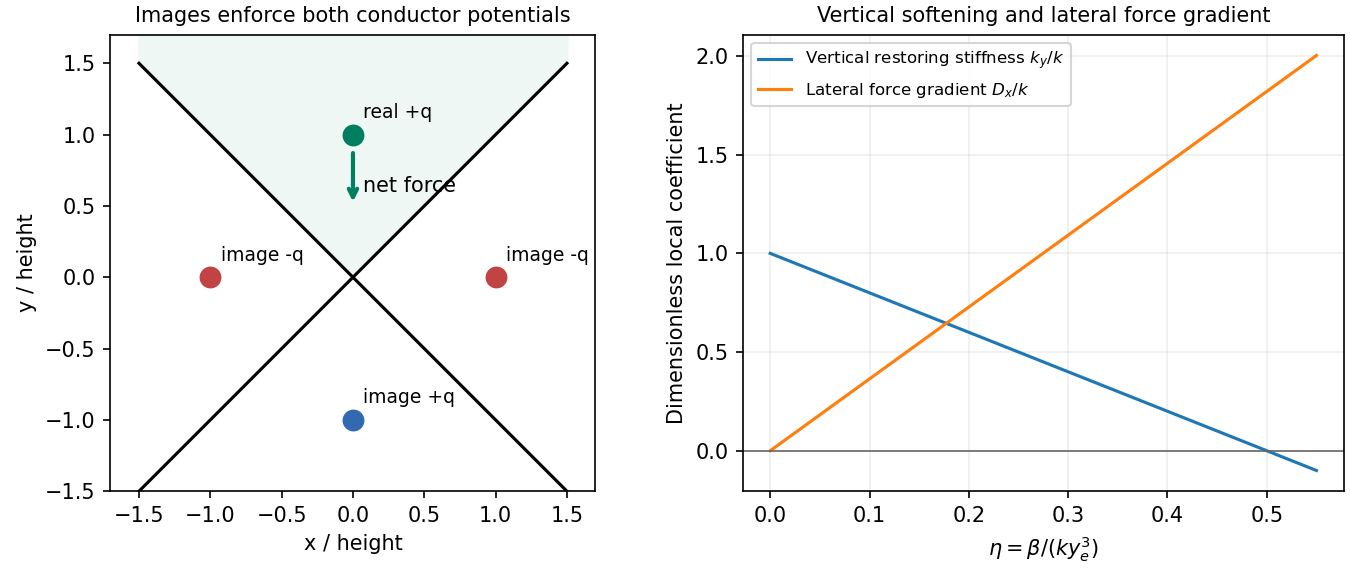
Original image-charge field construction and the opposite signs of vertical softening and lateral electrostatic stiffness
. Details. For distributed inductance and capacitance , a small segment obeys and . Differentiation gives and . For a forward wave,A backward voltage wave has current . This sign matters at an impedance discontinuity.
The source figure is the stacked-strip parallel-plate transmission line geometry, despite its use of the word coplanar. Gauss's law gives . Opposite surface currents give magnetic field between the strips by Ampère's law; the magnetic flux per unit length is , hence . ThereforeNo numerical is given; the impedance is appropriately left in terms of that ratio. The line is taken to be nonmagnetic and lossless.
Increasing the gap by changes to and to , so while is unchanged. voltage and current continuity at the step giveConsequently the voltage and energy-flux transmission coefficients areHere amplitudes are peak voltage amplitudes, with mean power . The reciprocal gaps have : equal reflected energy but opposite voltage phase. A voltage transmission coefficient above one does not imply energy gain.
For a finite impedance section of a transmission line, put and . Multiple reflections inside the altered section interfere. Summing their geometric series, relative to the first boundary,Transmission is unity at and minimal at , with minima . Resonances are separated by ; the long-wavelength limit also transmits fully. Matching the far termination removes end echoes, not the two internal reflections.
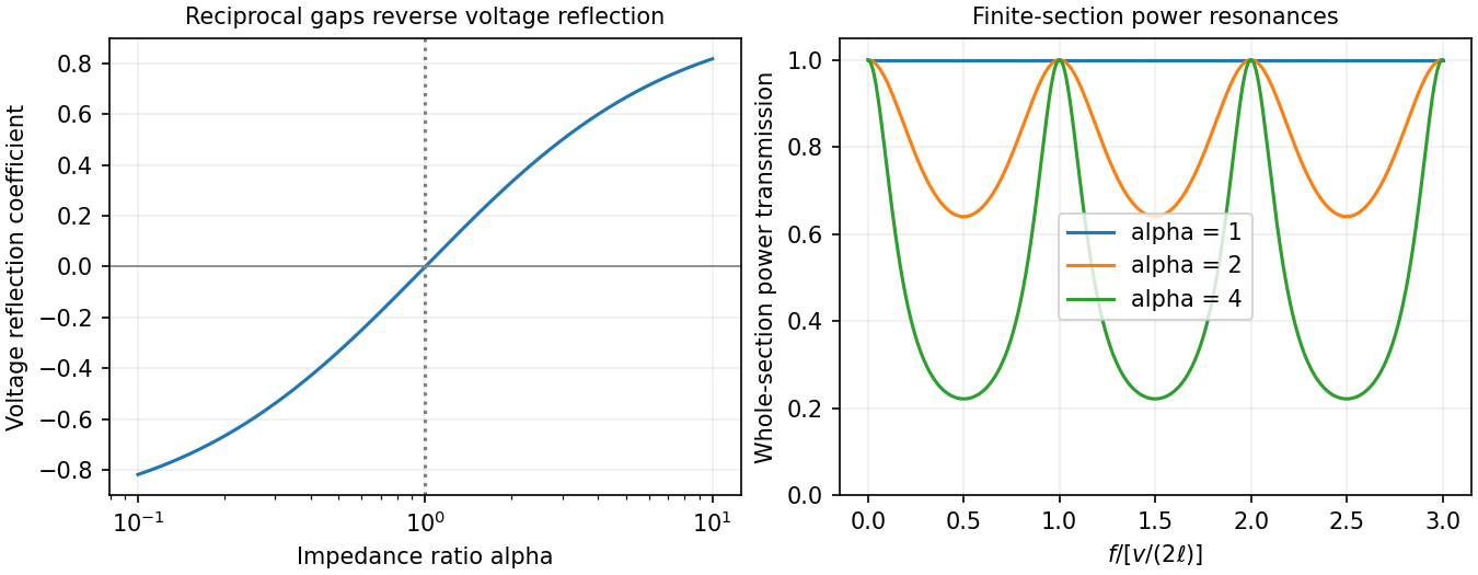
Original calculated power transmission through a finite changed-impedance section between matched lines
. Details. For a moving loop, Faraday's law of induction is , where is the local wire velocity, , and the oriented boundary and surface follow the right-hand rule. For a fixed loop the motional term vanishes. Lenz's law is the minus sign: the induced response opposes the change of linked flux, not necessarily the applied field itself.
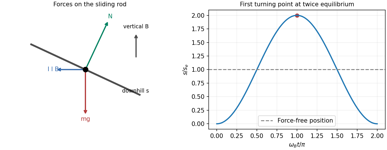
Let increase downhill and choose positive current to produce an uphill magnetic force. The normal component of the imposed field is , so the changing external flux is . With initially zero current and no resistance, conservation of flux linkage gives . The rod feels gravity vertically downward, a rail reaction normal to the slope, and magnetic force of magnitude horizontally uphill. Its downhill component is ; its normal component presses the rod into the rails, giving .
The inductive oscillation of a sliding rod on inclined rails follows fromThe magnetic force is not itself parallel to the rails. Defining and , release from rest givesThe first stop occurs at ; the rod then returns and oscillates between and . At the force is zero but the speed is maximal. Mechanical potential energy is reversibly exchanged with kinetic energy and ; a perfectly conducting circuit provides no damping.
For the resistive long-time drift of an inductive sliding rod, with loop resistance , useJoule heating damps the transient oscillation. On sufficiently long rails the asymptotic motion is steady sliding, not permanent rest:The zero-resistance model has persistent oscillations; its late-time limit cannot be interchanged with taking . These results assume , smooth contacts, negligible rod self-inductance and constant geometry.


For cold, collisionless, unmagnetized electrons with stationary heavy ions, . Therefore andThis is the cold collisionless plasma dielectric response. For a propagating transverse wave, , so in vacuum and in plasma, where . Equivalently and for .
Converting the density gives , so and . At ,At an interface without independently imposed surface charge or sheet current, tangential and normal are continuous, with the electron response included in the effective permittivity. Normal need not be continuous; the induced electron charge is represented by that response. In a convention treating it explicitly as a surface charge, the normal vacuum-displacement jump equals that charge instead.
For the downward transmitted wave, transversality gives . The measured field therefore has , so and . Tangential phase matching givesFor inferring incident power from a transmitted plasma field, choose and . Their magnetic fields have opposite directions. The two tangential conditions areHence and . Since these are peak phasor amplitudes,This is incident power per area perpendicular to its propagation. Per area of the interface the incoming normal flux is . The reflected sign is a phase reversal, not negative reflected energy.
At , the relative permittivity is negative and there is no propagating transverse bulk wave. The field decays evanescently into the plasma and the ideal collisionless half-space reflects all incoming normal power. Collisions would allow absorption; a complex refractive index here does not by itself imply dissipative heating.
Articles by others on the same topic
There are currently no matching articles.