In macroscopic matter with free charge density and free current density ,The electric displacement and magnetic field strength encode the material response.
These are the Maxwell equations after separating free and bound material sources.
Constitutive relations specify how matter responds to fields. A homogeneous isotropic linear electromagnetic medium obeys and .
Electromagnetic permeability relates magnetic flux density to magnetic field strength through in an isotropic linear medium.
Vacuum permeability is the magnetic permeability appearing in the vacuum Maxwell equations. In SI, it relates vacuum magnetic field strength to magnetic flux density through and obeys , where is the speed of light and the vacuum permittivity.
A linear anisotropic medium has constitutive relations and . Symmetric, time-independent tensors make the field-energy density a quadratic form.
Here permittivity is a tensor, so the electric displacement need not be parallel to the electric field.
Birefringence is the existence of different optical propagation constants for different eigenpolarizations in an anisotropic material. It provides the propagation-mode separation needed for adiabatic optical following in a twisted nematic.
Two different refractive indices can produce two displaced images, as in the calcite double-image experiment, or a phase retardation between overlapping components, as in a waveplate. Spatial separation concerns where energy flux travels; phase retardation concerns the relative wave phase. A specimen need not show two visibly separated images to have birefringence.
A known retarder inserted in a polarization microscope to compare phase delay with an unknown specimen. Parallel slow directions add signed retardations; a slow direction paired with a fast one subtracts them. General relative angles require composing polarization transformations rather than scalar addition.
A quartz retarder used to identify specimen fast and slow directions through changes of interference colour or compensation. Its own retardation and orientation must be specified before unique final colours can be predicted.
For a lossless uniaxial dielectric, , where is the angle between the wave vector and optic axis. Along the axis , while perpendicular propagation gives .
Colour produced when wavelength-dependent interference selectively transmits or reflects part of white light. Between crossed polarizers, a uniform birefringent plate gives a factor , where is its optical path difference. The observed colour also depends on illumination and the spectral response of the observer.
A birefringent plate with retardation gives . At non-extinction azimuths, wavelengths satisfying are removed by a crossed analyser. At a principal-axis azimuth every wavelength is extinguished.
Birefringence produced by subwavelength structure rather than solely by intrinsic crystalline anisotropy. For ideal dielectric lamellae, continuity of tangential electric field gives , while continuity of normal electric displacement field gives . The unequal effective permittivities give different principal refractive indices.
Linear birefringence means that two orthogonal linear polarizations have different refractive indices. Their different propagation phases produce phase retardation. In a lossless waveplate, with fast-axis angle and slow-minus-fast retardation , the Jones matrix, up to a common phase, isusing time dependence . Circular birefringence instead has circular eigenpolarizations.
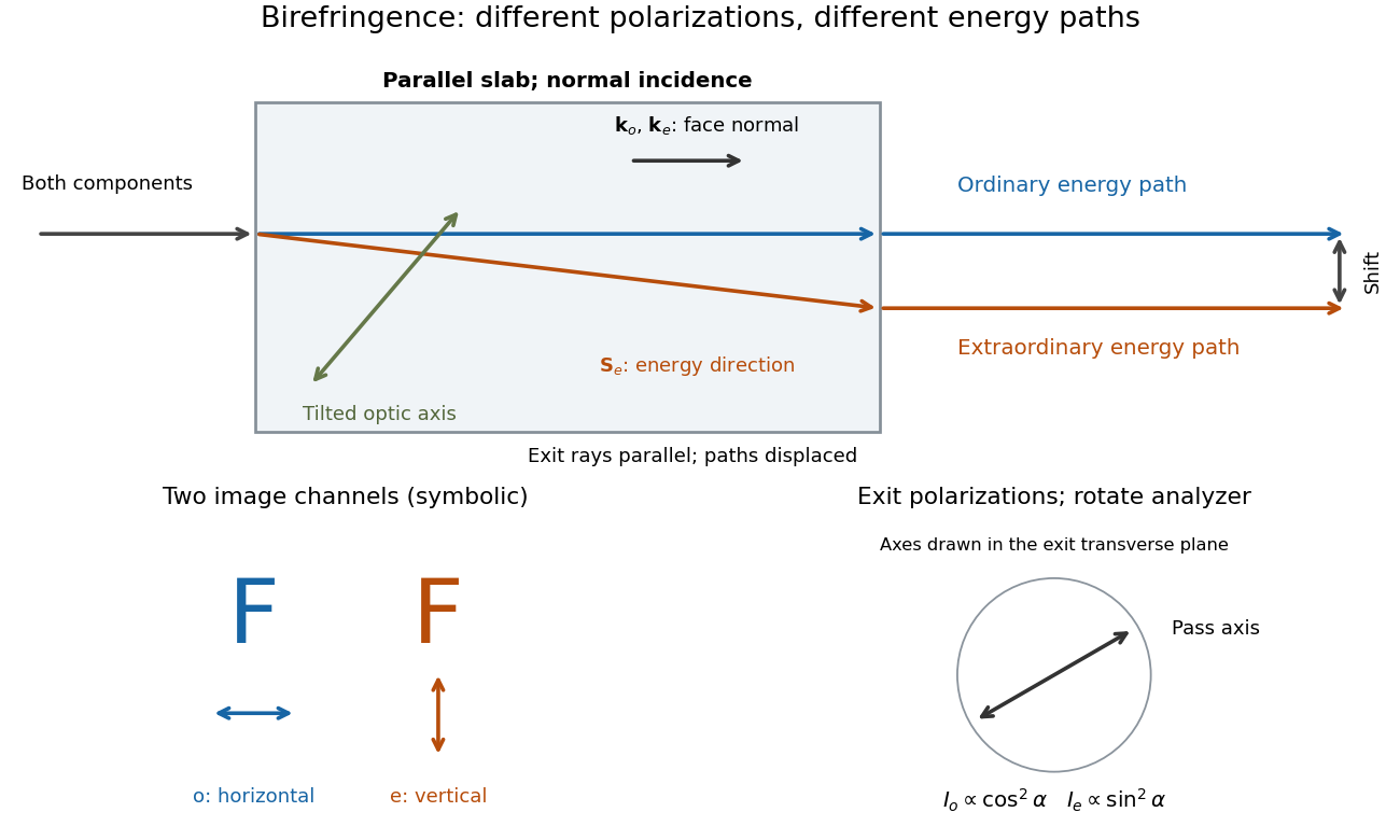
Place a clear calcite specimen on a transparency bearing printed words on an overhead projector. The projected readout is two copies of the lettering. Put a rotatable linear polarizer after the specimen: suitable orientations suppress one copy or the other. These are the actual apparatus and observations in the University of Iowa demonstration.[ref]
Polarization - Calcite & Iceland Spar by University of Iowa, Department of Physics and Astronomy. Demonstration 6H35.15, Equipment and Procedure: crystals, polarizers, printed overhead transparency, two sets of words and selective extinction; final note on natural defects
For a useful control, remove the specimen while keeping the transparency, projector and screen fixed: the doubling should disappear. Replace it, hold it stationary and rotate only the polarizer; complementary brightness changes distinguish two linear polarizations from an accidental duplicate transparency. These are suggested controls, rather than additional reported measurements. Ideally the two copies obey complementary Malus's law curves, and , with angle measured from the exiting ordinary wave's linear polarization. Unequal maxima do not invalidate the test. Finite polarizer extinction, poor focus and specimen defects limit visibility; image separation alone does not determine either refractive index without the specimen geometry.

A transparent, nonmagnetic linear anisotropic dielectric is uniaxial when two principal permittivities agree. With the optic axis along , its permittivity tensor has the displayed diagonal matrix form. Here and are principal refractive indices at a specified frequency; is not the extraordinary wave's index in every direction.[ref]
The symmetry direction of a uniaxial optical medium. For a wavevector along it, the two refractive indices coincide: there is no birefringence for that propagation direction, even though .
The ordinary wave's electric field is perpendicular to the plane containing the wavevector and optic axis. Its refractive index is direction independent at fixed frequency.
The extraordinary wave's electric displacement field lies in that plane and is perpendicular to the wavevector; its electric field need not be. For angle between the wavevector and optic axis,Thus and .[ref]
A short derivation starts from the existing plane wave in an anisotropic dielectric equation. Put and , with angular frequency and vacuum speed of light . The component gives the ordinary wave relation . The determinant of the system givesSubstituting and yields the displayed directional refractive index.
The extraordinary wave's Poynting vector can differ in direction from its wavevector. The latter specifies wave phase propagation, while the former specifies energy flux. This angular separation is walk-off.[ref]
In the lossless, nondispersive model above, take the gradient of to obtain the group velocity, parallel to the Poynting vector. If its angle to the optic axis is , this gives . Consequently the extraordinary wave generally carries energy away from its wavevector direction. An internal wavevector normal to a slab face therefore does not guarantee a normal energy path. Birefringent walk-off vanishes at and ; the latter direction still has unequal refractive indices. This is a useful waveplate geometry: overlapping components can acquire phase retardation without spatial splitting. A thin specimen, insufficient imaging resolution, or excitation of only one linear polarization can also hide a double image, for different reasons.
For a lossless nonmagnetic uniaxial optical medium, the electric displacement field of a plane electromagnetic wave is perpendicular to its wavevector. The magnetic field is perpendicular to the plane containing the electric field and wavevector, while the Poynting vector is perpendicular to the electric field in that same plane. Thus the angle between and equals the walk-off angle between energy flow and phase propagation. At normal incidence on a parallel slab of thickness , a lateral separation of the ordinary and extraordinary exiting rays gives , while . The output rays can be parallel even though their internal energy paths differ.
A waveplate uses birefringence to change polarization of an electromagnetic wave through phase retardation. Its fast axis has the smaller refractive index, hence the larger phase velocity; its slow axis has the larger index. Consider normal incidence with the optic axis in the plate face, so both components follow the same straight path. A linear polarization at to these axes excites equal wave amplitudes.
A complementary experiment uses two sheet polarizers with a cellophane sheet between them. First cross the polarizers and remove the sheet: the field is dark. Insert and rotate the sheet about the beam: light returns at intermediate orientations, but extinction recurs at two perpendicular orientations. The sheet has changed the polarization of an electromagnetic wave, without requiring a resolved double image. With white light, different wavelengths can produce different transmitted colors.[ref]
The Feynman Lectures on Physics, Volume I by Richard Feynman and others. I §33–3, Fig. 33–3 and the paragraphs describing removal, rotation and white-light colors of cellophane
. Brightness alone does not establish circular polarization: an ideal rotating linear polarizer also gives orientation-independent light intensity for unpolarized light.A detected lower-path photon with vertical polarization evolves under an angle-dependent Jones matrix. For fast-axis angle , its horizontal amplitude is and its vertical amplitude is . A later vertical-path probability therefore depends on the plate orientation and on whether the earlier lower-path event has been conditioned on.
The relative phase accumulated by orthogonal eigenpolarizations is . A quarter-wave plate has relative phase modulo , while a half-wave plate has modulo .
For the overlapping monochromatic wave components, let be the thickness and the vacuum wavelength. Define using the slow and fast refractive indices. With complex amplitude convention , the accumulated slow-minus-fast phase difference isThis is the optical path difference expressed as a wave phase. It is a signed accumulation convention; with the opposite time convention the sign reverses. The outgoing polarization of an electromagnetic wave depends on modulo . Here the positive slow-minus-fast differs from the signed principal-index used in the parent birefringence entry when .
For an original worked example, stipulate at and a uniform thickness . These are design assumptions, not measured material data. The optical path difference is , soIt is a quarter-wave plate. At the same wavelength and refractive indices, doubling to gives , a half-wave plate. A thickness increase changes by , or ; retaining the same birefringence at would instead give for the plate. Real refractive indices also vary with wavelength, so this last calculation explicitly neglects optical dispersion.
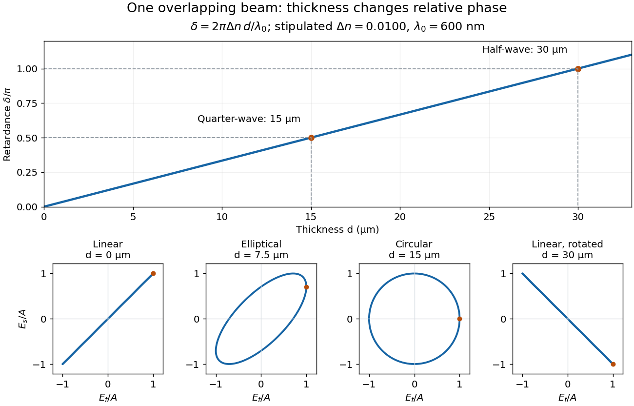
Phase retardation grows with thickness while overlapping components change polarization of an electromagnetic wave
. The stipulated , model gives quarter-wave and half-wave thicknesses of and . Insets trace the normalized electric field at a fixed point for equal fast/slow wave amplitudes, with and . The intermediate ellipse, circle and rotated line require no spatial beam separation. Details.
For these equal transmitted wave amplitudes, orthogonal projection onto a polarizer crossed with the initial linear polarization gives a simple independent readout. After removing a common wave phase, the component complex amplitudes are proportional to ; orthogonal projection onto gives . Squaring its modulus yields : zero at , one half at , and one at . This assumes ideal polarizers, negligible specular reflection and wave absorption, overlapping components and stable relative wave phase. It measures a periodic function of phase retardation, so one brightness measurement cannot determine the thickness uniquely.
A zero-order quarter-wave plate satisfies . Its retardance error at nearby angular frequency is . Taylor expansion gives the title expression, including material dispersion. Neglecting that dispersion yields . A half-wave plate made from twice the same material thickness has exactly twice this phase error. Common propagation phase can be removed from its Jones matrix without changing polarization.
A quarter-wave plate gives a quarter-cycle phase retardation. Equal transmitted wave amplitudes initially in linear polarization at become circular polarization; unequal wave amplitudes generally give elliptical polarization. Reversing the sign reverses the traversal of the same circle.
Take a half-wave plate with fast axis at to a linearly polarized input, followed by a quarter-wave plate at a further , so the second axis is at to the input. With shared quarter-wave retardance error and half-wave error , use and . Rotating each matrix into the input axes and multiplying gives and the title expansion. Its first-order change is common phase only, so the output remains circular to first order. This input-specific local compensation does not prove a frequency-independent quarter-wave operator for arbitrary input across a finite spectral band.
Suppose the unknown ideal elements are a linear polarizer and a quarter-wave plate, and the two unknown sources are unpolarized and circularly polarized. Test both element orders while rotating their relative axes and monitoring output intensity. Only circular input followed by the quarter-wave plate and then the polarizer gives complete modulation: the plate makes linear light and the analyzer obeys Malus's law. Polarizer-first output is constant half-intensity because the following lossless plate changes polarization but not intensity. Unpolarized input is constant in either order. This identifies both elements and both sources without comparing source brightnesses.
Two rotatable ideal quarter-wave plates can transform a fixed circular polarization into any pure polarization represented by a Jones vector. Use time dependence , and input . Every target polarization ellipse can be written, up to a common phase, as , with signed ellipticity angle . The first quarter-wave plate at produces linear polarization at . The second, at , therefore produces the required target. The two angles supply the two independent parameters of pure polarization.
For a reciprocal ideal quarter-wave plate followed by a mirror at normal incidence, use the same fixed transverse laboratory axes for the forward and returning Jones vectors. If the axes coincide with the plate's fast and slow axes, each pass has Jones matrix up to a common phase factor. A polarization-independent mirror has scalar reflection coefficient , so the returned Jones vector is . The plate acts twice as a half-wave plate, rather than undoing its phase retardation.
For input linear polarization at angle to the fast axis, the returned line is at modulo . At it is perpendicular to the original line. An axis-aligned input instead returns along the same line. General elliptical polarization requires its full input Jones vector; no unique returned state follows from the word “polarized” alone. The propagation direction reverses, so comparing descriptions of circular polarization must also specify the viewing convention.
Take a linear polarizer and a reciprocal quarter-wave plate in fixed physical transverse axes. A near-normal isotropic mirror has up to global phase. If the source/detector side encounters P before Q, the round-trip matrix is . Reversing the filter gives , which transmits half an initially unpolarized intensity. The result is double-pass rejection, not optical nonreciprocity; changing direction without changing the input polarization does not preserve the same physical input state.
A half-wave plate reverses the relative sign of the two components. For initial linear polarization at angle to the fast axis, the outgoing line is at modulo . The input therefore rotates by .
Circular birefringence means different refractive indices for opposite circular polarizations. In a transparent isotropic medium, their relative wave phase changes rotate the direction of transmitted linear polarization; optical activity gives the solution measurement and convention.
The rotatory power is the rotation of transmitted linear polarization per unit path length, in . With equally transmitted circular eigenmodes and time convention , their accumulated phase difference gives . For uniform circular birefringence, . Generic linear birefringence need not admit one rotation angle common to all incident polarization directions. In a weak longitudinal Faraday effect, , with signed Verdet constant .
Articles by others on the same topic
There are currently no matching articles.