For this question use phasors with time factor , so an electrical impedance is . The same electric current flows through all components of a series circuit, and their voltages add by Kirchhoff's voltage law. Hence the total series electrical impedance isThe individual steady sinusoidal currents and their phase relations are derived in the following three parts. The diagram normalizes each current by its own amplitude, so it compares phase differences without mixing unlike physical units.
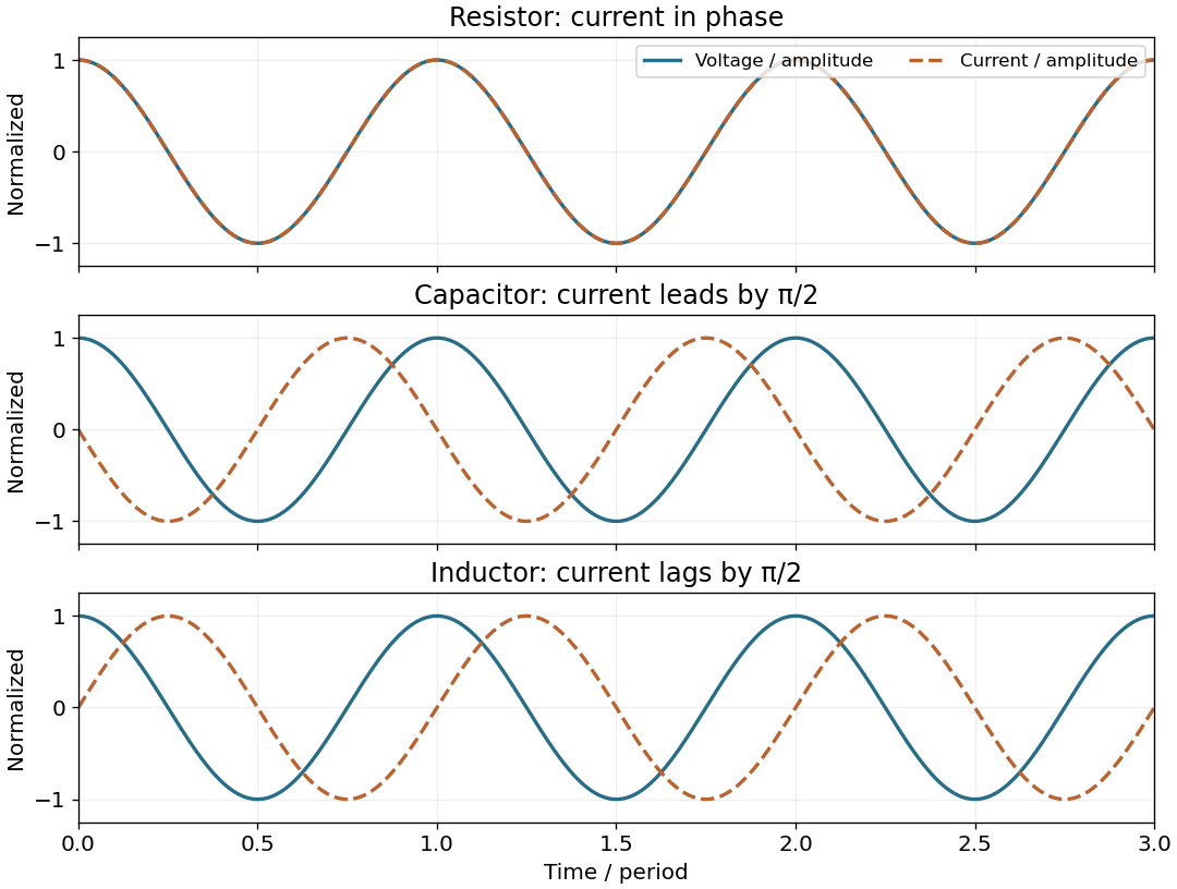
Normalized voltage and current waveforms for a resistor, capacitor and inductor; capacitor current leads and inductor current lags by a quarter cycle
. Details. 
For an inductor, . In the steady AC solution with no added constant electric current,The electric current lags the voltage by . An ideal inductor can also sustain an arbitrary DC current, fixed by initial conditions; it is excluded from this steady sinusoidal comparison.
The output is measured across the capacitor. The voltage divider gives the RC low-pass filter transfer functionThereforeThe amplitude ratio tends to and the phase shift to zero as . For , the amplitude ratio is asymptotic to and the phase shift tends to .
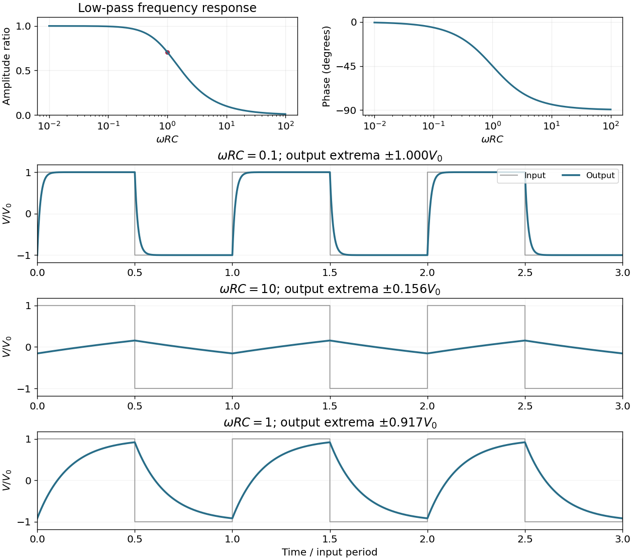
The RC low-pass filter amplitude and phase response, and periodic responses to a symmetric square-wave input at three values of
. Details. 
The half-power amplitude condition for the RC low-pass filter gives . Since angular frequency is positive,At this cutoff angular frequency, the output amplitude is smaller by and the phase shift is .
The RC low-pass filter satisfies for . With zero initial capacitor voltage, the first-order linear differential equation givesThe output is continuous at switching and approaches with time constant .
For explicit sketches take a symmetric, 50% duty cycle square wave with levels . The source does not specify levels or duty cycle; a unipolar 50% wave follows by adding its mean and rescaling. Let and be the positive output extremum in the periodic steady state. The square-wave response of an RC low-pass filter hasextended periodically. The extremum formula follows by imposing and . It makes the three regimes below quantitative, including their finite amplitudes.
When , each half-cycle lasts many time constants, so . The output nearly follows the two input levels, with exponentially rounded transitions lasting order . It remains continuous rather than making ideal vertical jumps.
When , the capacitor voltage changes little during each half-cycle. Thus , giving an approximately triangular output. Its extrema areThe finite but small triangle is centered on zero for the chosen zero-mean input. A nonzero input mean shifts the output mean by the same amount.
When is of order one, the output consists of visibly curved exponential charging and discharging arcs, with neither long flat plateaus nor nearly straight sides. At ,The output is continuous and lags the abrupt input transitions; its precise shape is the periodic solution given in the parent part.
Articles by others on the same topic
There are currently no matching articles.