The electric field of a signed point electric charge in vacuum follows Coulomb's law:For the conducting plane, the method of images replaces each charge at height by an image charge at height . The real and image electric fields have cancelling tangential components and equal normal components at the surface. Thus the electric field at a conducting plane from axial point charges, just above the point directly below them, isNumerically,The surface value means the air-side limit. Inside the ideal conductor the electrostatic electric field is zero; its discontinuity across the surface is supported by induced surface charge. Omitting the image charges would give half the external answer.
For steady currents in vacuum, Ampère's circuital law isHere is an oriented closed curve, its tangent line element, and the signed electric current through a spanning surface oriented by the right-hand rule. A circular contour about a straight infinite wire has constant tangential magnetic field, so . The Lorentz force on a length of the other wire is . ThereforeThe right-hand rule makes the force on each parallel, same-direction current point toward the other wire.
The continuity equation for electric charge is . Taking the divergence of the magnetostatic Ampère's law would instead require . The displacement current repairs this conflict: using Gauss's law, , so the Ampère-Maxwell equation isIn the parallel-plate capacitor, neglect fringing fields and take . A circular Ampère loop of radius encloses displacement current . Therefore the magnetic field between circular capacitor plates has phasor and amplitudeIt is zero on the axis, grows linearly with radius, and is azimuthal by the right-hand rule. This is a quasistatic approximation: in addition to , the uniform-field model requires and excludes the edge region. The answer gives the oscillation amplitude, rather than a time-independent instantaneous magnitude.
The intensity of an isotropic radiator at distance is the radiated power divided by spherical area: . For a locally plane far-field electromagnetic wave in air, its mean Poynting flux is , where the vacuum wave impedance is . ThusandBoth conventions are given because “field strength” alone does not specify RMS or peak. This estimate treats the stated transmitter power as radiated power and ignores ground reflection and absorption.
A grating spectrometer places an illuminated narrow slit at the front focal plane of a collimator. The resulting parallel beam reaches the diffraction grating at known incidence, here taken normal. A rotatable telescope focuses each outgoing diffracted parallel beam onto its crosshair or detector. Align the slit with the grating rulings, focus the collimator at infinity, and illuminate many grooves across a suitable aperture. A narrow slit supplies sufficient spatial coherence and prevents slit width from blurring the angular separation; the telescope must also resolve the two images.
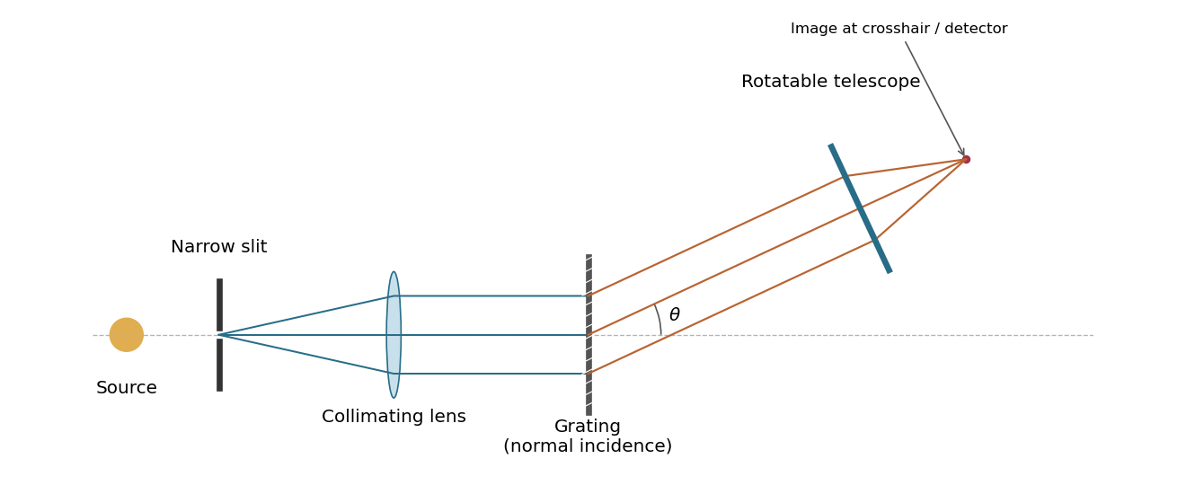
A grating spectrometer with a narrow source slit, collimator, normally illuminated diffraction grating and rotatable observing telescope
. Details. The groove spacing is . The grating equation at normal incidence is . For diffraction order ,ThereforeThe ideal resolving power of a diffraction grating is , so the Rayleigh criterion for this doublet requires about illuminated grooves, spanning roughly . This is an ideal lower bound; finite slit width, aberrations and detector resolution can require a larger usable aperture.
Use an ideal inverting summing amplifier, grounding the non-inverting input and connecting the two sources through resistances and . A feedback resistance gives the desired weights. Operational-amplifier negative feedback makes the inverting node a virtual ground, and negligible input current lets Kirchhoff's current law give
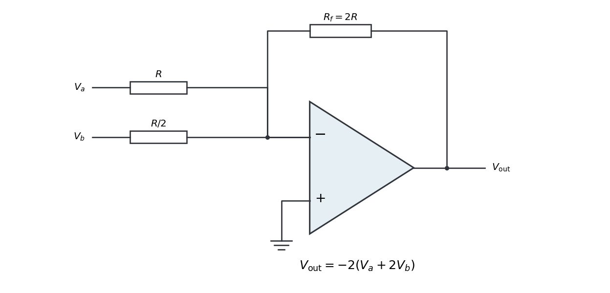


Replacing the feedback resistor by a capacitor makes a weighted op amp integrator:The initial capacitor charge determines the integration constant. A nonzero DC weighted input produces a ramp; a real operational amplifier eventually reaches its output-voltage limit. A parallel feedback resistance can limit drift while preserving integration over an appropriate frequency range.
The integral and differential forms of Gauss's law in vacuum areFor an isolated spherical conductor, symmetry gives outside and zero inside. Taking electric potential zero at infinity, . Thus the capacitance of an isolated conducting sphere isCharging from zero gives the electrostatic potential energyThis is also the integral of electric field energy density outside the sphere. The later insertion into a coaxial cylindrical capacitor conserves its electric charge, not its original isolated electric potential.
Initially the isolated sphere has . After insertion without contact, its charge remains . In the long-cylinder approximation, with the sphere far from the openings, neglect electric flux escaping through the ends. A Gauss surface running through the shielding metal and closed by end sections of negligible flux then encloses zero net charge. Its cavity wall therefore carries . Since that cylinder is isolated and initially neutral, its outside wall carries . The grounded outer cylinder supplies charge on its inside wall, terminating the annular electric field lines.
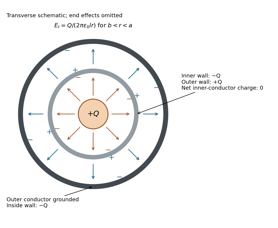
Transverse schematic of a charged sphere inside a neutral coaxial capacitor: induced charges and electric field lines, with no field inside the conducting walls
. Details. 
For positive , the cavity electric field lines run from the sphere to the inner wall, while annular electric field lines run from the outside of the inner conductor to the grounded outer conductor. Negative reverses their directions. The transverse picture is schematic: exact cavity fields depend on the sphere's position and the ends. The following annular formulas neglect end effects and place the sphere well inside the long cylindrical assembly.
For , a coaxial Gauss surface of length encloses net charge : the sphere and the cavity-wall charge cancel, leaving on the outside of the inner conductor. In the long-cylinder approximation,The electric field points radially outward for . End effects and axial nonuniformity near the openings are excluded by the ideal coaxial cylindrical capacitor approximation.
The grounded outer cylinder fixes . Integrating the annular electric field inward givesEquivalently, the coaxial cylindrical capacitor has and carries charge , so . The original sphere potential is used to infer its conserved charge; it is not the final potential of the sphere or of the inner cylinder.
The Biot-Savart law isHere is the current-element position, follows the electric current, and is the observation point. For a circular current loop, transverse components cancel on the axis. Each element contributes axial factor in addition to the inverse-square distance. Integrating around length gives the on-axis magnetic field of a circular current loopwith axial direction set by the right-hand rule.
For a finite straight wire parametrized by , at perpendicular distance , the Biot-Savart law givesThe direction is azimuthal about the current axis by the right-hand rule. In the hairpin, the semicircle contributes and each semi-infinite straight segment contributes . For the indicated current, all three contributions point out of the page. Thus the magnetic field at the center of a hairpin wire is
For this question use phasors with time factor , so an electrical impedance is . The same electric current flows through all components of a series circuit, and their voltages add by Kirchhoff's voltage law. Hence the total series electrical impedance isThe individual steady sinusoidal currents and their phase relations are derived in the following three parts. The diagram normalizes each current by its own amplitude, so it compares phase differences without mixing unlike physical units.
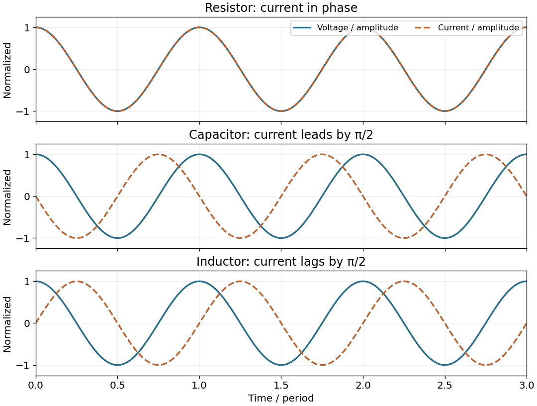
Normalized voltage and current waveforms for a resistor, capacitor and inductor; capacitor current leads and inductor current lags by a quarter cycle
. Details. 
For an inductor, . In the steady AC solution with no added constant electric current,The electric current lags the voltage by . An ideal inductor can also sustain an arbitrary DC current, fixed by initial conditions; it is excluded from this steady sinusoidal comparison.
The output is measured across the capacitor. The voltage divider gives the RC low-pass filter transfer functionThereforeThe amplitude ratio tends to and the phase shift to zero as . For , the amplitude ratio is asymptotic to and the phase shift tends to .
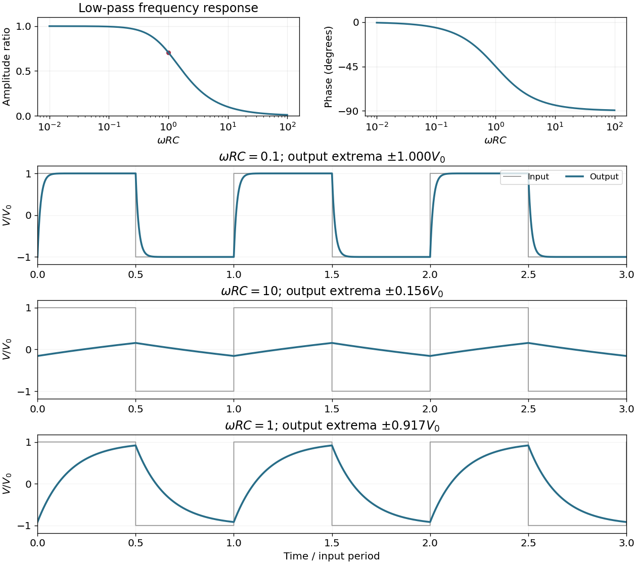
The RC low-pass filter amplitude and phase response, and periodic responses to a symmetric square-wave input at three values of
. Details. 
The half-power amplitude condition for the RC low-pass filter gives . Since angular frequency is positive,At this cutoff angular frequency, the output amplitude is smaller by and the phase shift is .
The RC low-pass filter satisfies for . With zero initial capacitor voltage, the first-order linear differential equation givesThe output is continuous at switching and approaches with time constant .
For explicit sketches take a symmetric, 50% duty cycle square wave with levels . The source does not specify levels or duty cycle; a unipolar 50% wave follows by adding its mean and rescaling. Let and be the positive output extremum in the periodic steady state. The square-wave response of an RC low-pass filter hasextended periodically. The extremum formula follows by imposing and . It makes the three regimes below quantitative, including their finite amplitudes.
When , each half-cycle lasts many time constants, so . The output nearly follows the two input levels, with exponentially rounded transitions lasting order . It remains continuous rather than making ideal vertical jumps.
When , the capacitor voltage changes little during each half-cycle. Thus , giving an approximately triangular output. Its extrema areThe finite but small triangle is centered on zero for the chosen zero-mean input. A nonzero input mean shifts the output mean by the same amount.
When is of order one, the output consists of visibly curved exponential charging and discharging arcs, with neither long flat plateaus nor nearly straight sides. At ,The output is continuous and lags the abrupt input transitions; its precise shape is the periodic solution given in the parent part.
The Huygens-Fresnel principle constructs a later wavefront as the envelope of secondary wavelets emitted from the earlier one. At a planar interface, take a time interval during which one point on the incoming front travels distance before reaching the interface, while the point that reached it first generates a wavelet of radius . The two right triangles share the interface segment, giving . Since the refractive index is , this yields Snell's law:The angles are measured from the interface normal. This geometric construction assumes homogeneous media and uses the propagation speeds at the given frequency.
Let be the angle inside the prism relative to the inward normal of face A. For the entry position shown, below the midpoint of A, and , the transmitted ray first reaches face B. Its incidence angle there is . If , a transmitted ray leaves B according to Snell's law. If , it undergoes total internal reflection at B and then reaches C. At the equality, transmission is grazing.
On the reflected route through this equilateral prism, the incidence angle at C is , so permits emergence from C. The one-reflection path through an equilateral prism is drawn alongside the direct-transmission route.
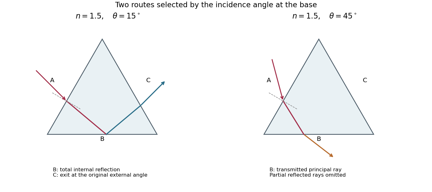
Principal transmitted ray paths through an optical prism: total internal reflection at B followed by exit at C, or direct refraction out of B
. Details. 
Real interfaces also produce partial Fresnel reflection below the critical angle; these additional weaker rays are omitted from the principal-path sketch. Which face a ray first reaches also depends on its entrance position, so the route statement uses the entrance geometry illustrated in the source.
For , the critical angle is . Here , so the condition at B is . At the threshold,Thus the requested positive-angle interval for strict total internal reflection isAt the upper equality the transmitted ray is grazing; normal incidence also gives total internal reflection at B if the endpoint is included. The distinction follows the question's positive-angle convention.
Take the positive horizontal direction along B. The initial direction is . Reflection at the horizontal face B reverses the vertical direction. At C, symmetry of the equilateral geometry gives internal incidence , so Snell's law makes the emerging angle to C's normal equal to . Its direction is therefore . Subtracting the incoming direction givesThis is the smaller angle between the incident and emergent propagation directions in the requested reflection interval. The cancellation of occurs because the entry and exit refraction angles have equal magnitudes; refractive index still determines whether the reflected route exists and where it exits.
Assume normal dispersion, so shorter visible wavelengths have larger refractive indices. At fixed external angle , the relevant criticality parameter iswhich increases with on this route. Thus shorter-wavelength blue light is totally reflected at B and reaches C, while longer-wavelength red light can transmit through B; green lies at the critical threshold. The prism separates the routes by wavelength near the green cutoff.
The totally reflected rays emerging from C have the same external deviation despite their different refractive indices; their exit positions can differ. Red light also has a partially reflected component by the Fresnel equations, so C is not a mathematically perfect colour cutoff. The observation concerns total versus partial reflection, with the transmitted B rays spread by wavelength. Anomalous dispersion, if present, would require the actual instead of the normal ordering assumed here.
Articles by others on the same topic
There are currently no matching articles.