The restoring, damping and electric forces on the electron give . Dividing by gives a Lorentz oscillator model withFor the convention, substitute . Then andThe time-averaged dissipated power isFor positive frequency the squared term is minimized to zero only at . Thus the power maximum is exactly at the undamped natural frequency, even though the displacement maximum is slightly shifted. Here . The half-power equation is , whose two positive roots areThis is the absorbed-power bandwidth of a viscously damped oscillator, exact within the model. Near resonance the profile is approximately a Lorentzian line shape. With ,For this wavelength linewidth of a damped-oscillator power resonance we used . The half-power wavelength endpoints are not exactly symmetric around , although that distinction is tiny here.
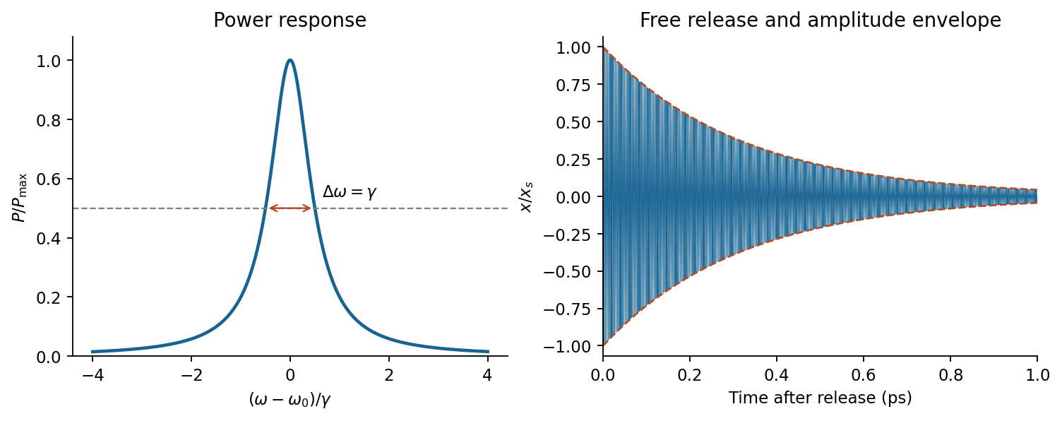

In a constant field the settled displacement is . On sudden removal, with zero initial velocity, the free motion isThe electron oscillates about its original equilibrium, losing the previously stored spring energy. The period is , the amplitude decay time is , and the cycle-averaged energy decay time is . This is the effective classical model supplied, not a prediction of the full hydrogen line radiation spectrum.
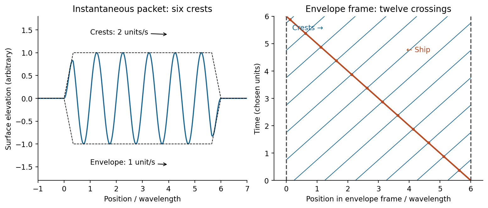
A wave packet is a localized superposition of nearby wavenumbers. Its rapid carrier crests have phase velocity ; the slowly varying envelope translates at the group velocity. Dispersion means that is not simply a constant times , so different carrier components have different phase velocities. Expand around :The integral is an envelope depending on , so at the central frequency. Neglected curvature causes packet spreading. For a deep-water gravity wave, , hence andFor crest crossings through a dispersive wave packet, an instantaneous group containing six crests has length approximately . A stationary ship takes to encounter the group; its crest-arrival frequency is . ConsequentlyIn the envelope frame the ship moves backwards at while crests move forwards at . Their relative speed is , explaining why counting a snapshot and counting crossings differ.

To estimate deep-water swell distance from period-dependent arrival times, assume a localized storm emits both periods at the same time and place, propagation is in deep water, and currents and refraction can be neglected. If its distance is , the arrival lag obeysWith , , about 4050 km. The corresponding travel times are three and four days. A moving or long-lived storm with frequency-dependent emission times would invalidate the unique distance inference.
At screen coordinate , the propagation length from aperture coordinate is . Its expansion has a constant term, a term linear in giving the observation angle, and a quadratic term of order . For , the quadratic wave phase is at most of order . Requiring it to be much smaller than one gives the sufficient condition ; higher terms are then smaller in the paraxial geometry. In the lens arrangement, put the source at the first lens's front focus, illuminate the grating with its collimated output, and put the screen at the second lens's back focal plane. This obtains the angular Fraunhofer diffraction pattern without a physically very distant screen.
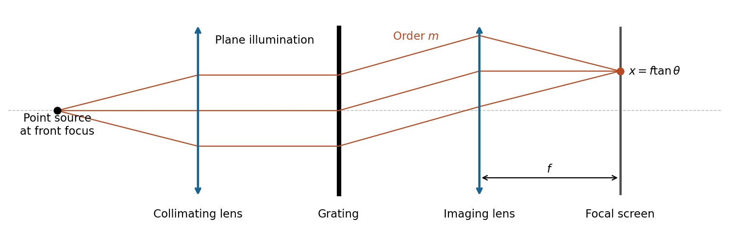

The slit pitch is . Normal-incidence maxima satisfy . Thus and, using rectilinear focal-plane geometry,The paraxial result is a roughly 4% lower approximation; an actual wide-angle lens's mapping depends on its design. The angular result does not depend on that convention.
For uniformly illuminated equal slits of width , the diffraction intensity has the formHere is unchanged when the incoming intensity is fixed. The broad single-slit diffraction envelope multiplies the narrow grating orders. At a principal maximum,The fixed-illumination grating peak change with slit width gives the changes from to areThe central peak increases by 125%, while the third-order peak decreases by about 89.4%. Separate normalizations to each central peak would hide this effect. The following width-specific solutions and profiles use a common incoming normalization.
With the order positions are unchanged from the grating equation, and the envelope's first zeros satisfy . Equivalently the first missing integer orders are . The third-order peaks remain appreciable. The displayed order-coordinate places all principal maxima at integers.
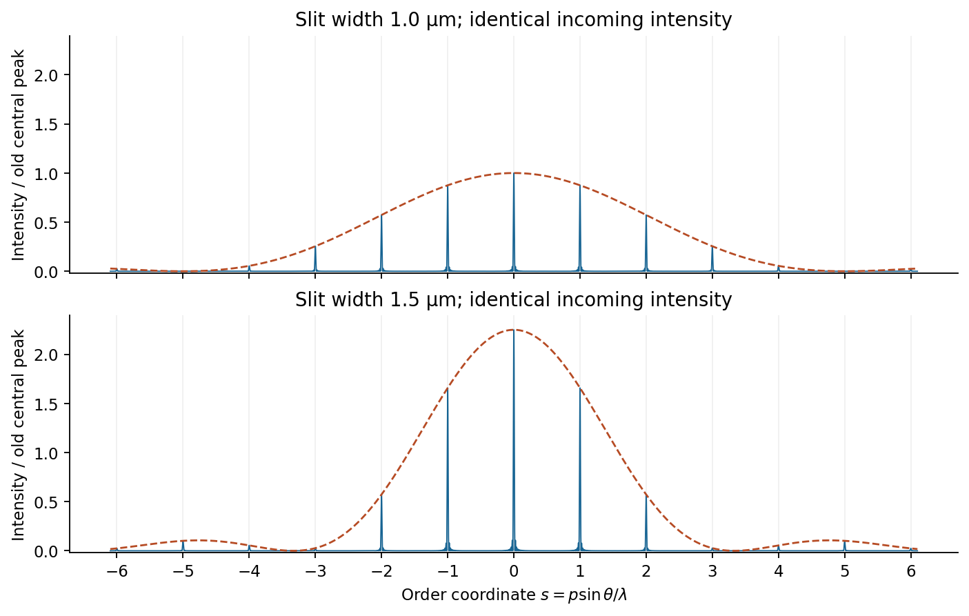
Slit-width envelopes on a common incident-intensity scale
. Original finite-array model with an illustrative 60 illuminated slits to make the peaks visible. Dashed lines show single-slit envelopes; the supplied slit pitch and widths set the peak ratios independently of this illustrative slit count. Details.
With the same principal maxima sit inside a narrower envelope, whose first zeros are at . The third order is now close to a zero and is strongly suppressed, whereas the central peak is taller. The first exact missing nonzero integer orders are ; is suppressed rather than identically missing.
A beam illuminates slits. The resolving power of a diffraction grating in order is , corresponding to a Rayleigh criterion separation . The separation therefore gives two well separated main peaks. The finite-grating incoherent doublet profile adds the mutually incoherent lamp intensities, not their amplitudes.
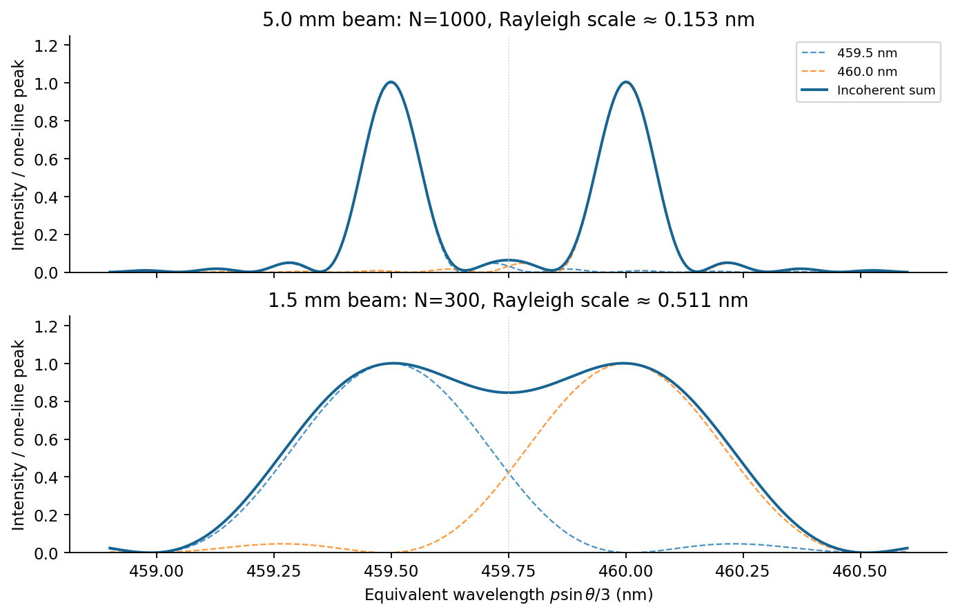
Third-order doublet for two illuminated grating widths
. Original finite-N intensity sums, with equal line strengths and narrow slits. The horizontal coordinate is the wavelength inferred from the third-order grating equation. Each component is dashed and their incoherent sum is solid. Details.
A beam illuminates only slits, giving and . The two main lobes broaden by compared with the wider beam. Their separation is slightly below the stated Rayleigh threshold: marginally unresolved by that criterion. This is not an assertion that the profile has only one maximum: the ideal equal-line sum still has two maxima and a modest central dip, as plotted. Inference from real data also requires adequate signal-to-noise ratio and a known instrumental profile.
The wave impedance is the travelling-wave field ratio ; for the stated nonmagnetic media it is . A reflection coefficient is a reflected-to-incident complex amplitude ratio with an explicitly chosen field orientation. With this reflection-amplitude sign convention, using the question's formula for incidence inside silicon givesWith a common tangential electric-field direction, the usual electric-field Fresnel equations instead give for this incidence. The printed formula corresponds to the opposite reflected-field sign convention, for example the magnetic amplitude convention. It gives the same reflectance and the same round-trip factor .
Each extra internal round trip multiplies the transmitted amplitude by , with . A geometric series therefore givesThis is Fabry–Pérot transmission from multiple reflections. Assuming lossless silicon with wavelength-independent , the full intensity transmittance between air regions isMaxima have , minima . Here , so within the specified tuning range the only maximum is , and the two minima are and . The contrast is
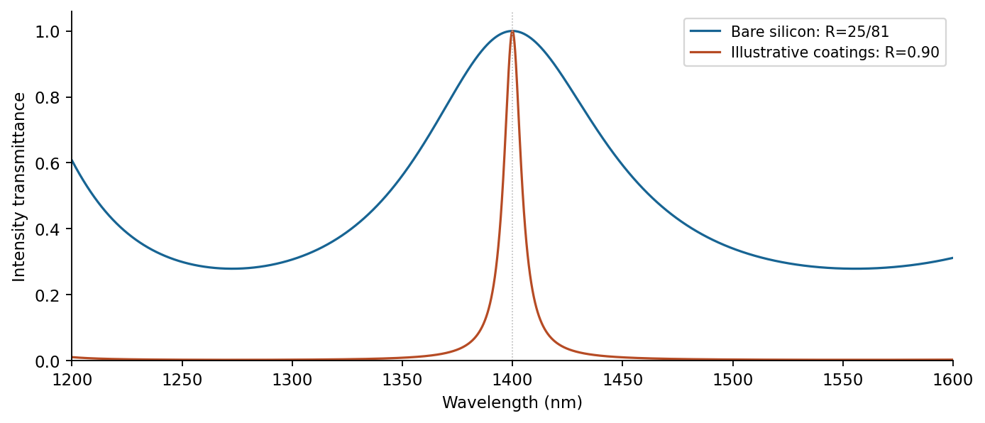
Transmission contrast and resonance narrowing with reflectivity
. Original ideal lossless symmetric-etalon curves. The coating example uses chosen R=0.90, unchanged optical thickness and zero additional round-trip phase. Details.
Identical highly reflecting coatings increase the finesse: transmission maxima become narrower and the intensity between them falls. Ideal symmetric lossless coatings retain ; absorption or unequal mirrors reduce it. The illustrated maxima stay fixed only because additional reflection wave phases are held unchanged. Real coating wave phases can also shift the resonances.
Articles by others on the same topic
There are currently no matching articles.