Original paper: Physics A (1), 28 May 2011; physical PDF pages 14–20.
For weak damping, the ringdown comparison bound for two resonator modes gives . Interpreting the stated loudness comparison as an intensity comparison,Therefore the information gives an upper bound, not a unique value:Equality would describe equal intensities at two seconds; the stated strict inequality allows every smaller positive consistent with the weak-damping model.
By linear scalar diffraction theory, complementary aperture transmissions and give under identical illumination. In Fraunhofer diffraction, away from the direct forward beam , so : the complementary screens have identical off-axis diffraction intensities. This is Babinet's principle. Their complex amplitudes, rather than their intensities, add. The direct beam is the exception; real conducting-edge vector effects are outside this ideal scalar statement.
For source and screen distances , the paraxial optical path excess at aperture radius is . The outer boundary of Fresnel half-period zone has excess , henceThis is the outer radius of the second zone, measured from the axis.
A conventional body-centred cubic cell contains two atoms, so its edge obeys . Taking gives . The neighbour shells of a body-centred cubic lattice have eight nearest neighbours that are at ; the six next-nearest neighbours lie along the cell axes. Thus the next-nearest-neighbour distance is .
For a free-electron Fermi circle in a square lattice, include two spin states per wavevector. A square cell of side supplies electrons per unit area; counting the disk of occupied states givesThe first Brillouin zone is . For , , so the circular Fermi surface lies wholly inside this square and encloses half its area. The figure uses the stated free-electron approximation; the lattice symmetry alone does not prescribe an exact circular surface.
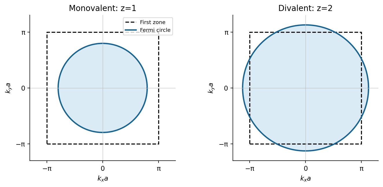

For , . The circle encloses one whole zone's area, crosses each face because , and misses the corners because . In a reduced Brillouin zone, fold the portions outside the square into neighbouring band branches. A weak periodic potential opens band gaps at crossings and deforms these pieces; divalence alone does not establish a band insulator.
The restoring, damping and electric forces on the electron give . Dividing by gives a Lorentz oscillator model withFor the convention, substitute . Then andThe time-averaged dissipated power isFor positive frequency the squared term is minimized to zero only at . Thus the power maximum is exactly at the undamped natural frequency, even though the displacement maximum is slightly shifted. Here . The half-power equation is , whose two positive roots areThis is the absorbed-power bandwidth of a viscously damped oscillator, exact within the model. Near resonance the profile is approximately a Lorentzian line shape. With ,For this wavelength linewidth of a damped-oscillator power resonance we used . The half-power wavelength endpoints are not exactly symmetric around , although that distinction is tiny here.
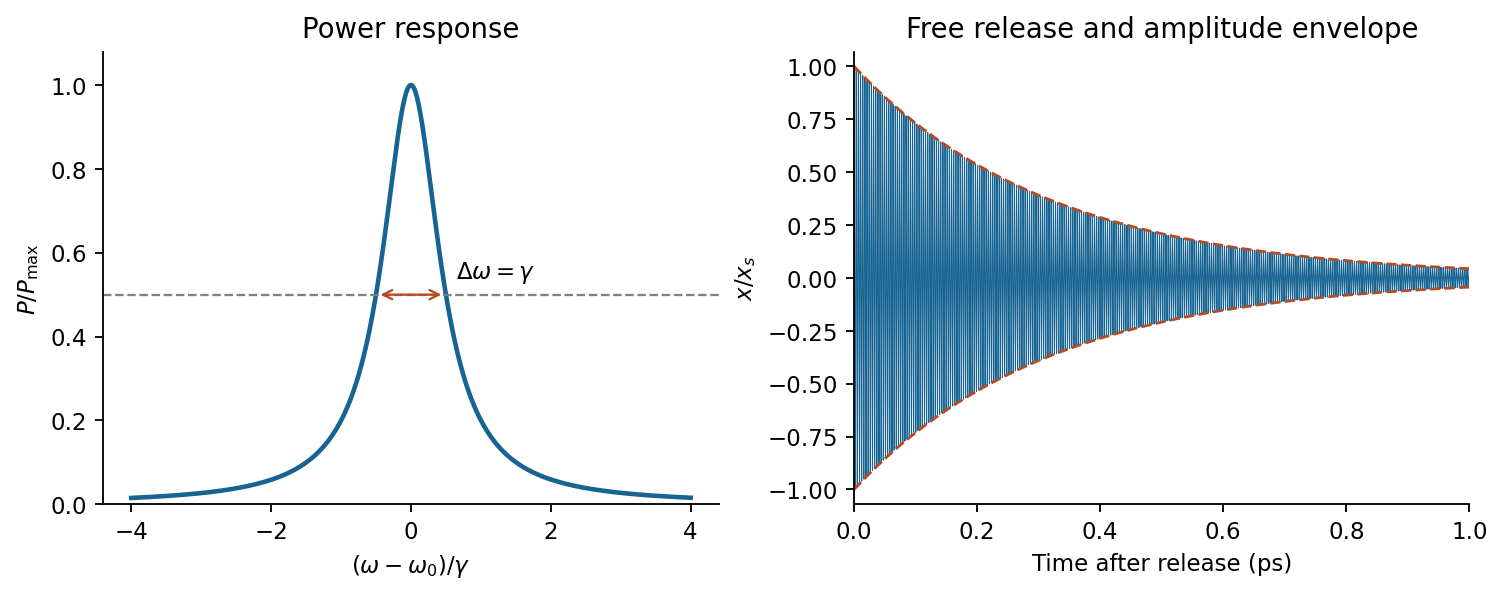

In a constant field the settled displacement is . On sudden removal, with zero initial velocity, the free motion isThe electron oscillates about its original equilibrium, losing the previously stored spring energy. The period is , the amplitude decay time is , and the cycle-averaged energy decay time is . This is the effective classical model supplied, not a prediction of the full hydrogen line radiation spectrum.
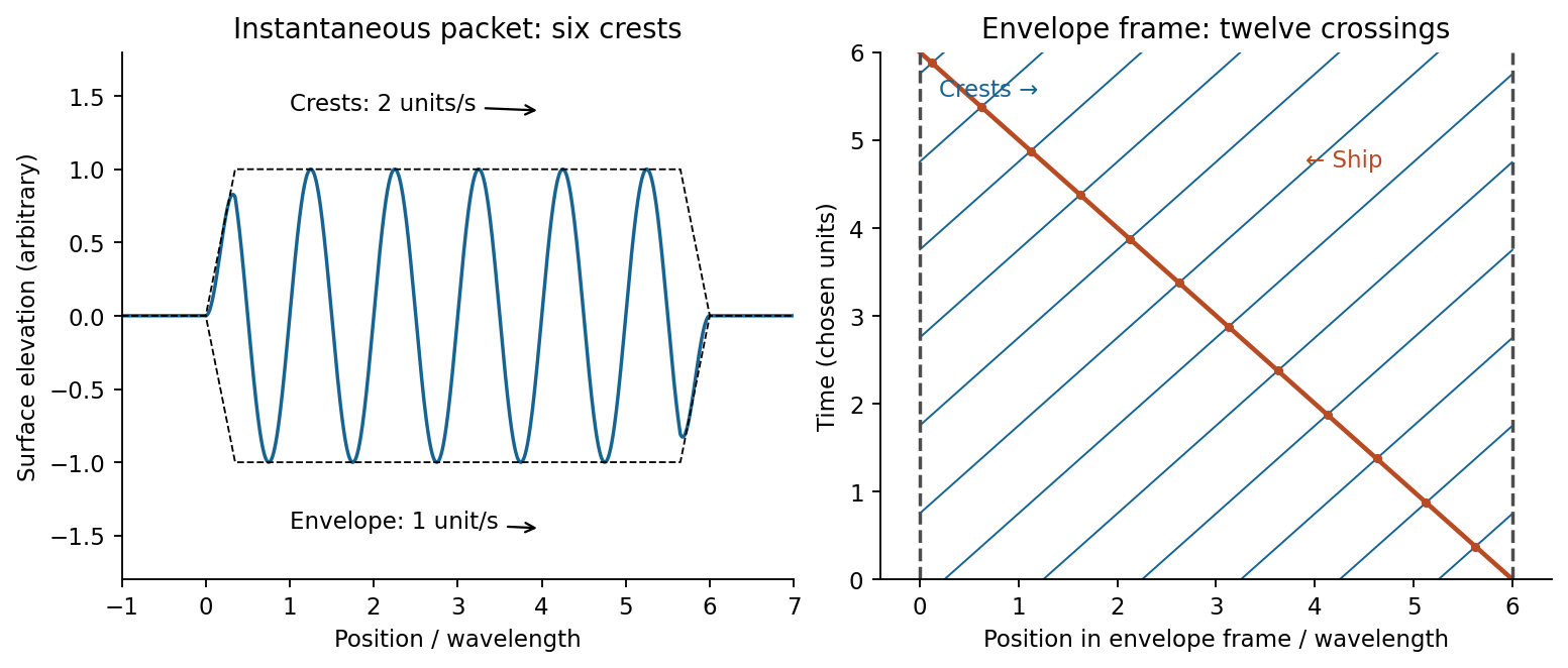
A wave packet is a localized superposition of nearby wavenumbers. Its rapid carrier crests have phase velocity ; the slowly varying envelope translates at the group velocity. Dispersion means that is not simply a constant times , so different carrier components have different phase velocities. Expand around :The integral is an envelope depending on , so at the central frequency. Neglected curvature causes packet spreading. For a deep-water gravity wave, , hence andFor crest crossings through a dispersive wave packet, an instantaneous group containing six crests has length approximately . A stationary ship takes to encounter the group; its crest-arrival frequency is . ConsequentlyIn the envelope frame the ship moves backwards at while crests move forwards at . Their relative speed is , explaining why counting a snapshot and counting crossings differ.

To estimate deep-water swell distance from period-dependent arrival times, assume a localized storm emits both periods at the same time and place, propagation is in deep water, and currents and refraction can be neglected. If its distance is , the arrival lag obeysWith , , about 4050 km. The corresponding travel times are three and four days. A moving or long-lived storm with frequency-dependent emission times would invalidate the unique distance inference.
At screen coordinate , the propagation length from aperture coordinate is . Its expansion has a constant term, a term linear in giving the observation angle, and a quadratic term of order . For , the quadratic wave phase is at most of order . Requiring it to be much smaller than one gives the sufficient condition ; higher terms are then smaller in the paraxial geometry. In the lens arrangement, put the source at the first lens's front focus, illuminate the grating with its collimated output, and put the screen at the second lens's back focal plane. This obtains the angular Fraunhofer diffraction pattern without a physically very distant screen.
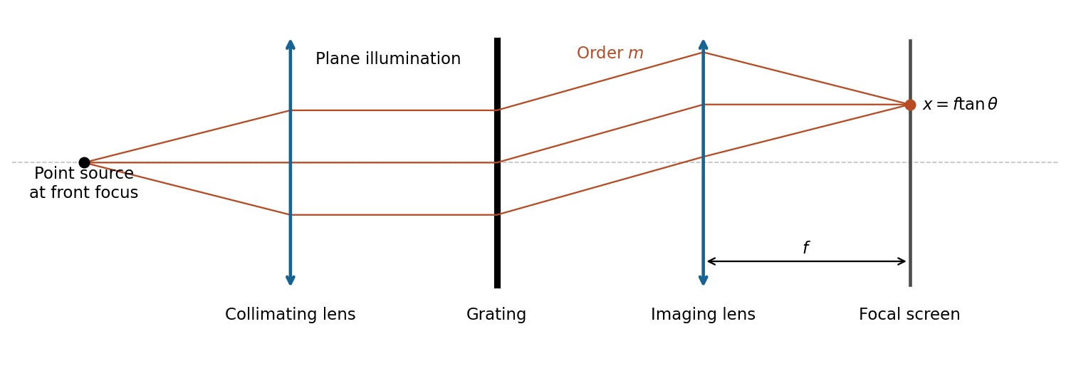

The slit pitch is . Normal-incidence maxima satisfy . Thus and, using rectilinear focal-plane geometry,The paraxial result is a roughly 4% lower approximation; an actual wide-angle lens's mapping depends on its design. The angular result does not depend on that convention.
For uniformly illuminated equal slits of width , the diffraction intensity has the formHere is unchanged when the incoming intensity is fixed. The broad single-slit diffraction envelope multiplies the narrow grating orders. At a principal maximum,The fixed-illumination grating peak change with slit width gives the changes from to areThe central peak increases by 125%, while the third-order peak decreases by about 89.4%. Separate normalizations to each central peak would hide this effect. The following width-specific solutions and profiles use a common incoming normalization.
With the order positions are unchanged from the grating equation, and the envelope's first zeros satisfy . Equivalently the first missing integer orders are . The third-order peaks remain appreciable. The displayed order-coordinate places all principal maxima at integers.
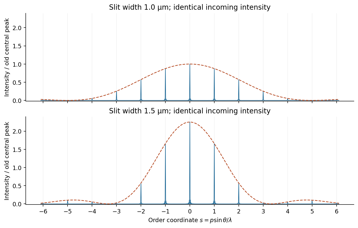
Slit-width envelopes on a common incident-intensity scale
. Original finite-array model with an illustrative 60 illuminated slits to make the peaks visible. Dashed lines show single-slit envelopes; the supplied slit pitch and widths set the peak ratios independently of this illustrative slit count. Details.
With the same principal maxima sit inside a narrower envelope, whose first zeros are at . The third order is now close to a zero and is strongly suppressed, whereas the central peak is taller. The first exact missing nonzero integer orders are ; is suppressed rather than identically missing.
A beam illuminates slits. The resolving power of a diffraction grating in order is , corresponding to a Rayleigh criterion separation . The separation therefore gives two well separated main peaks. The finite-grating incoherent doublet profile adds the mutually incoherent lamp intensities, not their amplitudes.
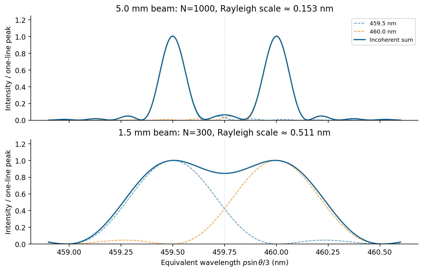
Third-order doublet for two illuminated grating widths
. Original finite-N intensity sums, with equal line strengths and narrow slits. The horizontal coordinate is the wavelength inferred from the third-order grating equation. Each component is dashed and their incoherent sum is solid. Details.
A beam illuminates only slits, giving and . The two main lobes broaden by compared with the wider beam. Their separation is slightly below the stated Rayleigh threshold: marginally unresolved by that criterion. This is not an assertion that the profile has only one maximum: the ideal equal-line sum still has two maxima and a modest central dip, as plotted. Inference from real data also requires adequate signal-to-noise ratio and a known instrumental profile.
The wave impedance is the travelling-wave field ratio ; for the stated nonmagnetic media it is . A reflection coefficient is a reflected-to-incident complex amplitude ratio with an explicitly chosen field orientation. With this reflection-amplitude sign convention, using the question's formula for incidence inside silicon givesWith a common tangential electric-field direction, the usual electric-field Fresnel equations instead give for this incidence. The printed formula corresponds to the opposite reflected-field sign convention, for example the magnetic amplitude convention. It gives the same reflectance and the same round-trip factor .
Each extra internal round trip multiplies the transmitted amplitude by , with . A geometric series therefore givesThis is Fabry–Pérot transmission from multiple reflections. Assuming lossless silicon with wavelength-independent , the full intensity transmittance between air regions isMaxima have , minima . Here , so within the specified tuning range the only maximum is , and the two minima are and . The contrast is
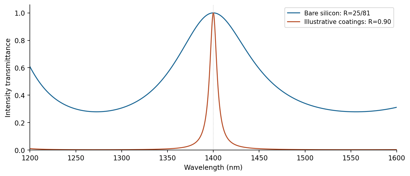
Transmission contrast and resonance narrowing with reflectivity
. Original ideal lossless symmetric-etalon curves. The coating example uses chosen R=0.90, unchanged optical thickness and zero additional round-trip phase. Details.
Identical highly reflecting coatings increase the finesse: transmission maxima become narrower and the intensity between them falls. Ideal symmetric lossless coatings retain ; absorption or unequal mirrors reduce it. The illustrated maxima stay fixed only because additional reflection wave phases are held unchanged. Real coating wave phases can also shift the resonances.
For this calculation define the net wavevector gained by the neutron as , the opposite of a common sample-transfer convention. Since ,The perpendicular neutron recoil and phonon absorption condition therefore requires . In the supplied periodic dispersion, interpret its as this transfer in the extended-zone representation of a phonon dispersion. Put and . Nonzero intersections obeyThere is no root in : there and . On the ratio increases strictly from to infinity, so exactly one root occurs. Nor can there be a higher root: gives , with strict inequality at the possible boundary. For , use ; throughout this short interval, since its minimum there is . Thus the only nonzero magnitude satisfiesSolving the exact dispersion, which is permitted instead of the linear approximation, givesA straight chord between the zone edge and the next zone centre gives . Its intersection solves , yielding and as a less accurate estimate.
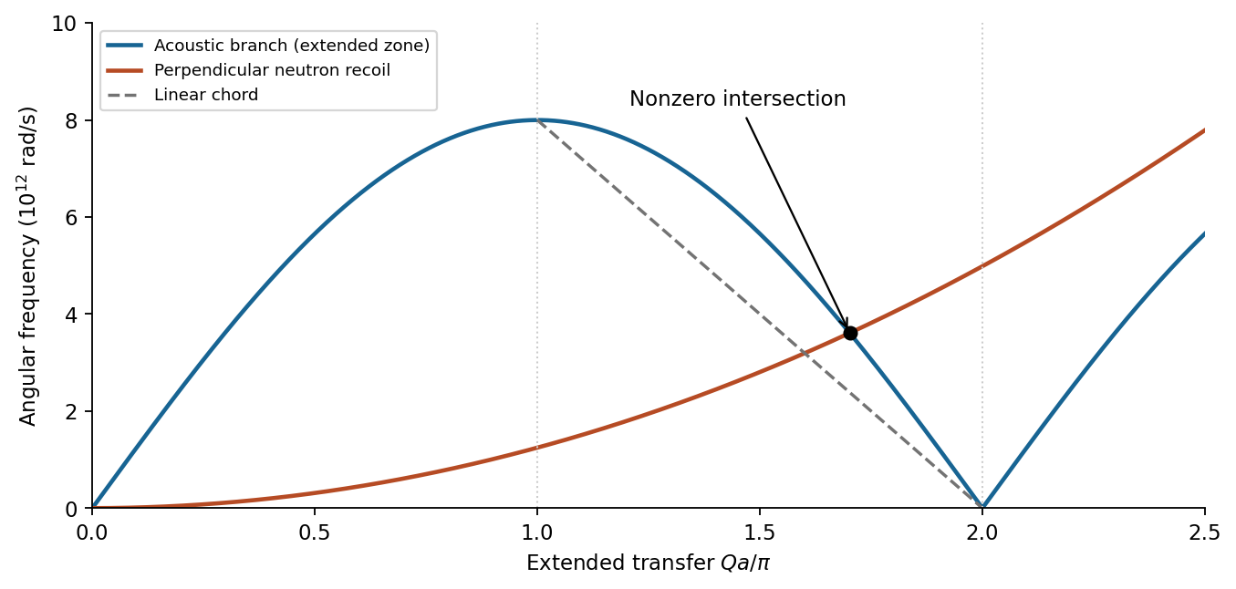

The reduced-zone phonon wavevector is along the chosen positive transfer direction. The difference is a reciprocal-lattice vector, not an additional independent phonon outside the first zone. At low temperature the absorption probability contains the Bose-Einstein distribution factor , which tends to zero. Here , so this absorption channel is strongly suppressed well below that scale. elastic scattering and kinematically allowed spontaneous phonon creation need not disappear.
For elastic scattering, and , where is a reciprocal lattice vector. In the ideal static crystal, coherent scattering obeys this lattice selection rule; the crystal as a whole can take the mechanical recoil with negligible energy. crystal momentum is defined modulo , not as unconstrained free-particle momentum.
For annihilation of a phonon ,For phonon creation,The signs follow whether the neutron gains or loses the phonon's energy and crystal momentum. These are one-phonon coherent inelastic neutron scattering conditions, with accounting for lattice periodicity.
For the electronic and lattice heat-capacity crossover in a monovalent metal, to obtain a numerical estimate from alone, assume monovalent potassium is a three-dimensional free electron gas with a parabolic band. Including both spins, the molar density of states is . Using the supplied approximate coefficient , rather than silently replacing it by , givesEquating it to the stated low-temperature Debye heat capacity yields the nonzero crossoverWe used and . This is self-consistently far below and the Fermi temperature. Using the exact Sommerfeld coefficient instead gives ; that is a change of approximation, not a discrepancy in the algebra. Without a band/DOS assumption, the supplied Fermi energy does not by itself determine .
For independent conduction-electron states labelled by band, wavevector and spin, combine those labels into . ThenHere counts the same spin and band states as the sum, and is fixed by the number constraint . The energy zero is a fixed band reference. Use the total DOS for total internal energy or the molar DOS for molar internal energy; these conventions must not be mixed.
In the harmonic approximation, sum over wavevector and phonon branch :The occupation factor is the Bose-Einstein distribution with zero phonon chemical potential; is the zero-point energy. A temperature-independent zero-point term does not contribute to the heat capacity in this fixed-frequency approximation.
Only states within an energy shell of width roughly around appreciably change occupation at low temperature. There are roughly such states and each excitation costs energy of order . Thus , giving . This is the thermal-shell estimate of electronic heat capacity; filled states far below are blocked by the Pauli exclusion principle. A smooth DOS and fixed particle number give the more precise Sommerfeld result to leading order.
For three-dimensional acoustic modes, and the mode count in a spherical shell is proportional to , giving phonon DOS proportional to . Thermally occupied modes have of order , so . Differentiation gives . At , all harmonic modes are classically populated; each has mean energy by equipartition. Thus the molar heat capacity tends to , the Dulong-Petit law. Anharmonic expansion and electronic contributions are not included in that lattice limit.
In Fourier transform spectroscopy, a scanning Michelson interferometer measures intensity against optical path difference rather than selecting one narrow wavelength at a time. After subtraction of the constant background, an ideal stationary source gives an interferogramA cosine Fourier transform recovers the spectral power density after instrumental calibration. A mirror displacement changes the round-trip path by ; the zero-path-difference burst aligns the scan, and a reference laser can calibrate the displacement.
Finite maximum path difference multiplies the interferogram by a window and convolves the recovered radiation spectrum with that window's Fourier transform. Thus is of order ; precise factors depend on scan range and resolution convention. Uniform path samples of separation need to avoid aliasing without bandpass information. interferogram apodization reduces sidelobes at the price of broader lines. The broad accepted optical throughput can be advantageous; the multiplex signal-to-noise advantage depends on detector noise and is not universal in photon-noise-limited measurements. Source drift during a scan, finite beam divergence, imperfect sampling and wave phase errors require control. The finite-window reasoning is the delay-range resolution in Fourier transform spectroscopy.[ref]
Introduction to Fourier Transform Spectroscopy by Julius Cohen. NBSIR 86-3339, chapters 13–16, printed pp.51–80: basic equation, apodization, resolution and sampling
A finite optical pupil spreads a point into a point spread function. In incoherent imaging an extended intensity distribution is convolved with that function; its Fourier transform is the optical transfer function, which attenuates and ultimately removes high spatial frequencies. For an ideal circular pupil the point response is an Airy disk. The Rayleigh criterion for two equally bright incoherent points isA microscope's object-space scale is of order , with the numerical factor depending on illumination and the criterion; measures the accepted ray cone. A larger pupil or shorter wavelength improves the diffraction scale. Aberrations, defocus, detector pixel sampling, motion, background and photon noise can worsen practical performance. Merely magnifying the same blurred image adds no information. Coherent sources require amplitude superposition instead of the incoherent intensity rule. Rayleigh resolution is a convention for separating a pair, distinct from the precision of localizing one isolated point; information does not abruptly vanish below it.
Boundary conditions quantize the transverse wavevector of an electromagnetic waveguide. For an ideal hollow rectangular conducting guide of sides , filled with a nondispersive medium of wave speed , a transverse electric mode of a rectangular waveguide or transverse magnetic mode of a rectangular waveguide obeysThe allowed integer pairs differ: TE permits one zero index, but not both; TM requires both positive. Here is the longitudinal propagation constant. Below cutoff is imaginary, so the mode is evanescent. Above cutoff,The positive branch approaches the straight line far above cutoff, while near cutoff its slope tends to zero. Different frequencies acquire different group delays and a pulse can spread. A wave phase speed above does not convey superluminal information; in this ideal guide energy transport follows the group velocity. A single hollow conductor cannot support a TEM mode; two-conductor guides can have a zero-cutoff TEM branch. Material dispersion, dielectric fibres and lossy boundaries require their actual dispersion relation and need not preserve the product rule.
Joining p-type and n-type regions initially allows majority carriers to diffuse across and recombine. Exposed negative acceptor charge on the p side and positive donor charge on the n side form a depletion region. Its electric field points from n to p and balances diffusion at equilibrium. The Fermi level is then spatially constant, while the conduction and valence band edges bend across the built-in potential; this equilibrium barrier cannot supply continuous power to a load.
forward bias makes p positive relative to n, reducing the barrier from to . electrons enter p material and holes enter n material, becoming minority carriers whose diffusion and recombination sustain the current. reverse bias enlarges the barrier and leaves a much smaller minority-carrier current until breakdown. The ideal diffusion model gives , the Shockley diode equation; depletion-region recombination, series resistance and breakdown limit this approximation. Minority-carrier injection on both sides is essential to the junction theory.[ref]
The Theory of p-n Junctions in Semiconductors and p-n Junction Transistors by William Shockley. 1949, pp.435–436: rectification, electron and hole currents, and injection
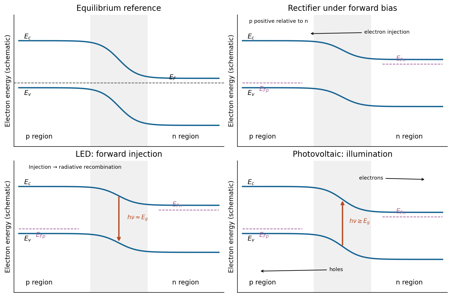
Junction band bending and three device functions
. Original schematic electron-energy diagrams, not quantitative band solutions. Equilibrium has one flat Fermi level; biased and illuminated panels indicate separate carrier quasi-Fermi levels. The photon arrows distinguish LED emission from solar-cell absorption. Details.
forward bias injects electrons and holes into a common active region. Their electron-hole recombination can emit a photon as an electron falls from a conduction-band state into an empty valence-band state, with approximately the band gap near the band edges. A direct band gap makes this radiative transition much more probable than an indirect gap requiring simultaneous phonon participation. Carrier confinement improves their overlap; nonradiative recombination and photon trapping reduce the external efficiency. This is spontaneous electroluminescence and does not require population inversion. The biased carriers have separate quasi-Fermi levels, rather than one global equilibrium Fermi level. The band-diagram downward arrow shows photon emission. As a concrete implementation, an InGaN/AlGaN double heterostructure was used for a bright blue junction LED.[ref]
Absorption of photons with creates electron-hole pairs, the upward band-diagram arrow. In the depletion region the built-in field drives electrons towards n material and holes towards p material; diffusion also delivers carriers generated within a diffusion length outside that region. Selective contacts collect the two signs. Illumination maintains a nonequilibrium quasi-Fermi-level splitting, allowing a voltage and useful current through an external load; it is the light, rather than the equilibrium barrier, that supplies the energy.
Taking forward diode current as positive, an ideal illuminated junction haspower is delivered where in this convention. Reflection, below-gap transmission, carrier thermalization, recombination and resistive losses limit real conversion; even an ideal single junction has radiative detailed-balance limits.[ref]
Detailed Balance Limit of Efficiency of p-n Junction Solar Cells by William Shockley and Hans-Joachim Queisser. 1961, Journal of Applied Physics 32, pp.510–519: radiative detailed-balance limit
Articles by others on the same topic
There are currently no matching articles.