In a charge-free region of homogeneous permittivity, Gauss's law and give Laplace's equation, . Prescribed surface electric potentials specify a Dirichlet problem. Its Uniqueness of the Dirichlet problem permits replacing conductors by fictitious charges outside the physical solution region: a harmonic candidate with the same boundary conditions is the physical solution. For an exterior problem its behaviour at infinity must also be prescribed. For a proof, subtract two candidate potentials to obtain with zero boundary values. Green's first identity gives , so is constant and its boundary value fixes it to zero. Conditions on a normal electric field instead determine a potential only up to an additive constant when the usual compatibility condition holds.
A cylindrical Gaussian surface around an infinite line charge gives . The electric potential difference is thereforeAn isolated infinite line charge has no finite potential zero at infinity. For the opposite pair, however, the logarithmic growth terms cancel and one can choose there. Define and . superposition givesOn ,Thus the circle, and its cylindrical extension, is an equipotential. This is an Apollonius circle: a constant ratio of distances gives a circle rather than a constant distance from either charge.
For the cylinder above the plane, call its centre height and set . The cylinder-plane image charges are at height and at height . Their distances are equal on the grounded plane, while their distance ratio is on the circular surface. The positive fictitious line lies inside the metal, so the exterior is charge-free and Uniqueness of the Dirichlet problem applies. A Gaussian surface enclosing the physical cylinder confirms that its charge per unit length is indeed . Its voltage isThe physical field energy per unit length at fixed cylinder charge is . Differentiate with respect to height, keeping and fixed:The electrostatic attraction per unit length of a cylinder above a plane is downward for either sign of charge. Placing the fictitious line at the cylinder centre would give the wrong answer at this separation. The long-cylinder approximation neglects the ends.
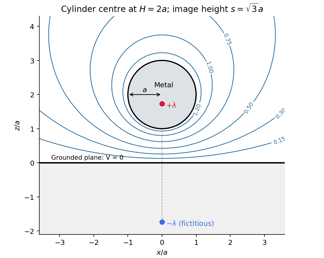
Original cylinder-plane image charges construction and exterior equipotentials
. Details. 
For fixed, magnetically linear geometry, self-inductance relates a coil's own magnetic flux linkage to its electric current, . mutual inductance relates the linkage in one coil to the current in the other, . These coefficients enter the induced electromotive forces through ; reversing a chosen winding orientation reverses the sign assigned to .
In the ideal confined-field toroid, a circular magnetostatic Ampère law contour encloses , soWrite for the height of the square cross-section. The inductance of a rectangular-section toroid follows by integrating the magnetic flux density over that cross-section; it cannot be replaced by its value at an arbitrary mean radius:Consequently, for winding normals chosen consistently,The equality means complete shared magnetic flux linkage; with leakage one instead has .
For the crack, use the radial-path approximation for a cracked toroid, with an air length on each path and core length . Continuity of the normal magnetic flux density at a crack face gives . HenceIntegrating the radial paths yieldsHere and : about a 53% reduction. The small ratio does not justify expanding in , which is about ten. The crack's low magnetic permeability gives appreciable magnetic reluctance. This is an estimate within a confined-flux model; actual redistribution near the slit is outside its accuracy. Narrow-gap circuit models assume small gap width relative to transverse dimensions and approximately directed flux.[ref]
Magnetic Circuits. §9.7, Example 9.7.1 and the paragraph after it: air-gap circuit approximation and need for a more general field solution
For the intact ring, ideal poloidal winding currents and the no-leakage boundary condition admit with zero radial and vertical components. It is curl-free inside the current-free core, divergence-free for uniform magnetic permeability, tangent to the core boundary, and has the required circulation; uniqueness of the Neumann problem removes an additional homogeneous scalar-potential field. This explains zero non-azimuthal components in the stipulated intact-ring idealization. A literal slit breaks that rotational symmetry, so zero transverse components everywhere is not exact for the cracked ring: magnetic fringing and flux redistribution occur. In fact, extending the approximate unchanged around a current-free core would give . Thus that radial-path calculation and a claim of exact purely azimuthal field in the cracked geometry cannot both be exact. The numerical answer above retains the intended circuit approximation while making its limitation explicit.
For a steady thin-wire electric current, the Biot-Savart law iswhere the source element follows positive current. For a circular loop, source points are and the observer is . Their cross product with has axial component ; transverse components integrate to zero. Thus the on-axis magnetic field of a circular current loop, multiplied by the number of coincident turns, isTake positive current counterclockwise as seen from . magnetic field lines pass upward through the loop and return around its exterior, closing rather than terminating. They fan outward above its centre and converge below it. The original numerical Biot-Savart law integration below illustrates these directions; the wire singularities are masked.
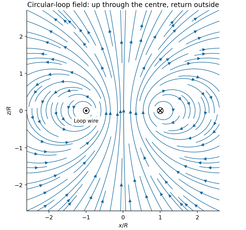
Original circular-loop magnetic field lines in a meridional cross-section
. Details. 
The axisymmetric magnetic field near a regular axis follows from Gauss's law for magnetism. In cylindrical coordinates, regularity gives , while symmetry gives . Integrate from the axis:A formal term is excluded by regularity. For the axial field decreases upward, so the radial component is outward, consistent with the sketch.
On the small receiving coil, . The Lorentz force has axial component . Contributions from the axial field cancel radially around the loop. ThereforeWith both currents giving magnetic dipole moments along and , this is attraction. Reversing one current reverses the force. The small coil has , so the result is exactly the leading magnetic dipole force . Equivalently . The approximation requires and negligible variation over the receiving coil; corrections begin at relative order .
Use peak-amplitude phasors with time factor and . Faraday's law of induction and the Ampere-Maxwell law giveIn the good-conductor limit , take the root with positive attenuation into the slab:The real physical field is . A thick slab excludes a returning wave from its rear face. The skin depth is the electric-field amplitude decay length; the intensity decay length is .
Faraday's law of induction fixes . The surface impedance of a good conductor and the complete transmitted magnetic field are consequentlyThe sign of the imaginary part belongs to the stated time convention. Average the Poynting vector using complex conjugation and the factor one half appropriate to peak phasors:As an independent energy check, , the mean Joule heating per unit volume.
Ohm's law gives and . Hence the averaged Lorentz force per unit volume isIntegrating through the illuminated half-space gives the positive inward radiation pressureFinally let be the vacuum wave impedance. Tangential-field boundary conditions at normal incidence give the electric-amplitude reflection coefficient . Since ,Here by surface energy balance. Combining the leading formulas gives , the nearly perfect-reflector limit. The displayed reflection expansion also assumes a good conductor relative to the incident vacuum wave, .
Articles by others on the same topic
There are currently no matching articles.