Inertia and principal directions. About the centre of mass, the inertia tensor isIt relates angular momentum and angular velocity by and gives rotational kinetic energy . The principal axes are orthogonal eigenvector directions of this real symmetric tensor; in that basis it is diagonal, with entries the principal moments of inertia .
Derivatives in a rotating frame. Write in a body-fixed orthonormal basis. Each basis vector rotates according to . Differentiating the components and basis separately proves the rotating-frame derivative formula,The body derivative differentiates the scalar components in that basis. A fixed pivot can replace the centre of mass when the corresponding angular-momentum balance is valid.
Euler equations. The inertial angular-momentum equation is . Since the principal moments are constant in the body frame, substitute :These are Euler's equations in the principal body frame.
Linear perturbation of free rotation. After the impulse, . Let to leading order and be small. The third Euler equation changes only at quadratic order, so the linear transverse equations areFor and , eliminate fromThis givesIts units are inverse square seconds. Positive gives a growing real exponential; negative gives bounded oscillatory perturbations.
For three distinct positive principal moments of inertia, the denominator of is positive. If is the largest moment, the two numerator factors have opposite signs, so . If it is the smallest, they again have opposite signs. If is intermediate, the two factors have the same sign, so . Thus the intermediate axis theorem givesFor the stable cases the body-frame wobble frequency isThe perturbation does not decay in the torque-free conservative model. For the intermediate moment, a generic small impulse excites the growing branch and eventually leaves the linear regime.
Put , with . ThenRotation about the symmetry axis is stable whether that axial moment is larger or smaller than the transverse moment. In fact and are exactly constant for a torque-free axisymmetric body: the transverse components rotate into one another at the stated body-frame frequency. Stability here means bounded wobble, not relaxation back to perfect axial rotation.
Both the magnitude of angular momentum and rotational kinetic energy are conserved after the impulse. At fixed , eliminate to writeThe fixed-angular-momentum energy test for principal-axis rotation makes the stability geometric. The largest moment gives a constrained energy minimum, the smallest a maximum, and the intermediate moment a saddle. Conservation of energy keeps a nearby motion near either isolated extremum, but a saddle permits departure in one direction while compensating in another. Thus both extremes are stable without dissipation; it would be incorrect to demand an energy minimum alone in this conservative problem.
The differential gravitational acceleration responsible for a tidal force is the difference between accelerations at separated points of a body. Relative to a freely falling reference point , a small offset experiencesThe tidal tensor has units ; the vector called in the source is the resulting differential acceleration, in . An actual differential force is this vector multiplied by the test mass. Measurable effects include relative motion of separated freely falling masses, radial stretching, transverse squeezing, deformation and, when self-gravity or strength is insufficient, disruption. A spatially uniform acceleration alone produces no tidal deformation.
For a point mass, . Along the outward radial direction, andThus a small radial displacement has differential accelerationThe farther point falls inward less strongly, so its acceleration relative to the reference point points outward. The formula is first order in .
Take a transverse offset . Its distance from the source changes only at second order, but the direction of the gravitational force changes at first order:in its first-order vector expansion. Subtracting the reference acceleration givesIt compresses the transverse separation. Together with the radial result, this is point-mass tidal stretching and squeezing, with tensor eigenvalues .
The extra radial term. A circular Kepler orbit has . In the frame rotating with the synchronously spinning body, centrifugal acceleration increases by across a radial offset . This adds the outward differential accelerationEquivalently, in the inertial frame the farther corotating point needs an extra inward centripetal acceleration , which gravity alone does not supply. The total radial stretching relevant to the static corotating body is therefore . This is the corotating point-mass tidal field. The source's “force” expression is per unit mass.
Self-gravitational survival. Denote the asteroid radius by , distinct from the orbital radius . Its mass is and its surface self-gravitational acceleration is . Compare this restoring acceleration with radial tidal stretching :The corotating tidal-disruption estimate for a uniform sphere isThis is the requested spherical local force-balance estimate, not an exact fluid Roche figure. It neglects deformation and material cohesion.
Why the asteroid radius cancels. At fixed density, self-gravitational surface acceleration scales as . The linear tidal acceleration also scales as . Their ratio is therefore independent of , provided so that the tidal expansion is valid. Density, rather than asteroid size, controls this estimate.
The terrestrial value. Convert to and use :This is distance from Earth's centre, not height above its surface.
Compression and stretch viewed on rotated faces. To isolate shear, take equal small principal strains , . A square with sides at to these directions becomes a rhombus: adjacent side lengths are unchanged to first order, but their right angle changes by . In axes rotated through , the same strain tensor has zero diagonal entries and off-diagonal entries of magnitude .
The pure shear from opposite principal strains therefore has engineering shear strain , not . Equal opposite principal stresses give purely tangential traction of magnitude on those rotated faces. HenceIf the compression and stretch are not equal and opposite, an additional dilatational strain remains; their deviatoric part still supplies shear.
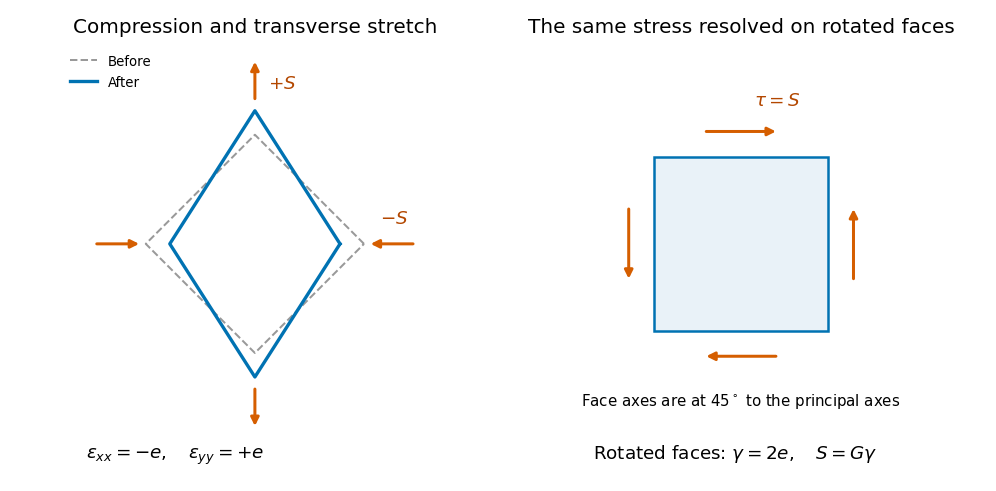
Original comparison of compression and transverse extension with the same stress resolved as shear on faces rotated through 45 degrees; deformation is exaggerated
. Details. 
The shaft's torsional stiffness. At radius , an end twist over length gives tangential displacement and shear angle . The local shear stress is . An annular area contributes torque , soThus torsion of a solid circular shaft givesHere is the polar second moment of area, in , not a mass moment of inertia. This is the transmitted torque magnitude; the shaft's restoring couple opposes the twist. The formula assumes small elastic shear and a circular uniform section.
Power is transmitted at rate , soFor , and , the polar second moment of area is . HenceThe density does not enter this static torsional deformation.
The torque rises linearly with elastic twist, so the stored elastic energy is the work integralUsing the transmitted torque and end twist,This is energy associated with deformation, distinct from the much larger kinetic energy of the whole spinning shaft.
For the uniform solid cylinder, the axial moment of inertia isThe rotational kinetic energy at isThis includes the shaft's bulk steady rotation; the small twist does not appreciably alter its mass moment at this order.
The torque difference. Let now be the local angular displacement, and take and the section constant. The local twist per unit length is , so the transmitted torque is . Across a short slice,Thusto first order in slice length.
The slice's angular acceleration. The slice's axial moment of inertia is . Its net torque is the difference of the end torques, soCanceling the common geometry gives the torsional waves in a solid circular rod,For the given steel, . The radius cancels because both torsional stiffness and slice inertia contain the same . This ideal one-dimensional wave model neglects dissipation and additional elastic modes.
Meaning and microscopic origin. For a Newtonian fluid, the dynamic viscosity measures tangential momentum transfer between fluid layers moving at different speeds. For the Newtonian shear considered here, , with units for . Molecular motion and collisions transport momentum across layers in a gas; intermolecular interactions contribute strongly in liquids. The resulting viscous forces oppose relative shear motion and convert organized kinetic energy to heat. The constitutive law is Newtonian and isotropic; incompressibility alone does not establish it.
Vertical force balance. Choose downward, as in the original diagram, and outward normal to the plate. In a uniform steady film, has zero advective acceleration and no along-plate pressure gradient. On a slice of thickness , the net shear force per unit face area is , while its weight per unit area is . ThereforeHere denotes the downward traction on a face with positive normal. The opposite face has the opposite traction orientation, accounting for the sign in the force difference.
Boundary conditions. At the fixed solid wall, the no-slip boundary condition is , with no normal penetration. At the free surface , neglect air shear, so and hence . The flat free surface has normal pressure , neglecting surface-curvature effects. These are a velocity condition at the wall and a stress condition at the free surface, not zero velocity at both boundaries.
The parabolic speed profile. Integrating from the shear-free surface gives . Thusand the wall condition yieldsIt is zero at the wall and largest at the free surface, where its gradient vanishes. The wall shear supports the downslope weight of the film per unit plate area.
Volume flux per unit width. Integrate through the depth:This is volume flow per unit length in , with units .
Inclining the plate. Keep normal outward from the plate and use downslope. The gravitational components are downslope and normal to the plate. For a uniform film of normal thickness , the steady slice equations areThe free-surface pressure condition givesUniform makes . The same no-slip and zero-surface-shear conditions then give the uniform gravity-driven Newtonian film,The component normal to the plate changes the hydrostatic pressure, while the tangential component drives the flow. The thickness is measured normal to the tilted plate.
The inclined-film volume flux. Integrating the new profile givesIt recovers the vertical result at and vanishes on a horizontal plate at fixed uniform depth. A varying depth, imposed pressure gradient or significant air shear would require additional terms; the solution here uses the uniform film specified by the simple draining-plate model.
Articles by others on the same topic
There are currently no matching articles.