The inertia tensor packages the moments of inertia about every axis through a specified point into one symmetric matrix. An axis still needs a direction: if is a unit vector, its scalar moment of inertia is . The same mass layout can therefore be easy to spin about one direction and harder about another. The inertia tensor also determines rotational kinetic energy and relates angular velocity to angular momentum in the appropriate rigid body model.
Take position vectors relative to , expressed in an orthonormal basis. For point masses , or a continuous distribution with mass density and ,Here is the Kronecker delta. Equivalently, using the identity matrix and an outer product,Every entry has SI units . The diagonal entries are axial moments of inertia; the off-diagonal entries carry a minus sign in this convention. Some texts instead define the integrals without the prefixed minus sign , , as their named off-diagonal quantities and put the minus signs into the displayed matrix. Check that convention before combining formulas. [ref] [ref]
The symmetric matrix is positive semidefinite, because its quadratic form isThe dot product and cross product identify this as a sum of squared distances when is a unit vector. A zero moment of inertia occurs precisely when all the mass lies on that axis, up to sets of zero mass. A genuine three-dimensional body with positive mass density in a volume has strictly positive axial moments of inertia. Do not confuse this inertia tensor with the mass second-moment tensor : they obey , where denotes the matrix trace.
If is fixed in an inertial frame and each velocity is , summing the individual kinetic energies and angular momenta givesThese formulas also describe angular momentum and rotational kinetic energy relative to the centre of mass of a translating rigid body. In that case the total kinetic energy in the inertial frame is . For a general moving point , the body's actual velocities include , so alone need not be its angular momentum about . [ref] [ref]
Changing the orthonormal basis changes components, rather than the physical distribution: if the columns of an orthogonal matrix are the new basis vectors expressed in the old basis, then . Changing the reference point is a different operation, governed by the tensor parallel-axis theorem. Both principal axes and principal moments of inertia must therefore be quoted with their reference point.
An inertia tensor can be isotropic even when the body is not a sphere. An example is a uniform thin disc of radius and mass , with a thin rod of length and mass attached normally at its center. The combined center of mass is one third of the rod length from the disc. Standard disc and rod moments and the parallel axis theorem give all three principal moments equal to , so . The angular momentum is therefore a fixed scalar times the angular velocity. In torque-free motion, conservation of the inertial angular-momentum vector makes the angular-velocity vector constant for every initial spin. Rotational symmetry of the shape is not required; equality of its second moments is enough.
If a rigid body's mass density is invariant under every rotation about an axis through its centre of mass, its inertia tensor in any orthonormal basis with third vector on that axis has the displayed form. In particular all transverse directions are principal axes with equal principal moments of inertia.
For a proof, let that axis be . In the defining integrals for the inertia tensor, a half-turn makes the and products change sign, so their integrals vanish. A quarter-turn makes the integral vanish and equates the integrals of and . Therefore all off-diagonal components vanish and . The values are and . No reflection symmetry in is needed.
For a uniform cube of side and mass , reflection symmetry makes central off-diagonal inertia components zero. Equal coordinate second moments are , so each diagonal component is . Thus every central axis is a principal axis. A nonspherical shape can have an isotropic central inertia tensor: that tensor measures only quadratic moments of the mass distribution, not the whole shape.
For a uniform ball of radius and positive mass , let be its centre of mass. Spherical symmetry gives the second-moment matrix , so the central inertia tensor is . The tensor parallel-axis theorem gives the displayed shifted tensor. For its eigenvector along has eigenvalue , while the two-dimensional orthogonal complement has repeated eigenvalue . Thus it is an isotropic tensor exactly at . Displacement along a chosen axis does not change that axis's moment; the transverse moments increase by .
For a nonnegative mass distribution relative to an origin, the second-moment matrix is and the inertia tensor is . Taking the trace gives the displayed inverse formula, which must be positive semidefinite. Conversely, any such can be realized by pairs of point masses along its orthogonal principal directions. Thus this is also a realizability test when total mass and dimensions are unrestricted. In principal coordinates it is equivalent to the moment-of-inertia triangle inequalities: , with cyclic counterparts. A symmetric positive definite matrix alone need not be a physical inertia tensor.
For a uniform planar lamina with and , put , . The Jacobian determinant is one, the mass is , and symmetry puts the centre of mass at zero. Uniform rectangular moments give , , . Substitution into yields the displayed inertia tensor. The in-plane principal moments of inertia are ; the perpendicular moment is their sum. This separates the geometric shear from the elementary rectangular integrals.
An exact planar example makes the off-diagonal entries tangible. Join four equal point masses with negligible-mass rigid connectors at , , and , where is a length. Their centre of mass is . Summing , and gives , and , respectively, soThe axis is a principal axis, and illustrates the perpendicular axis theorem. The axis is not a principal axis: angular velocity gives angular momentum , which points in a different direction. A bearing can enforce fixed-axis rotation despite this difference, supplying the necessary transverse torque.
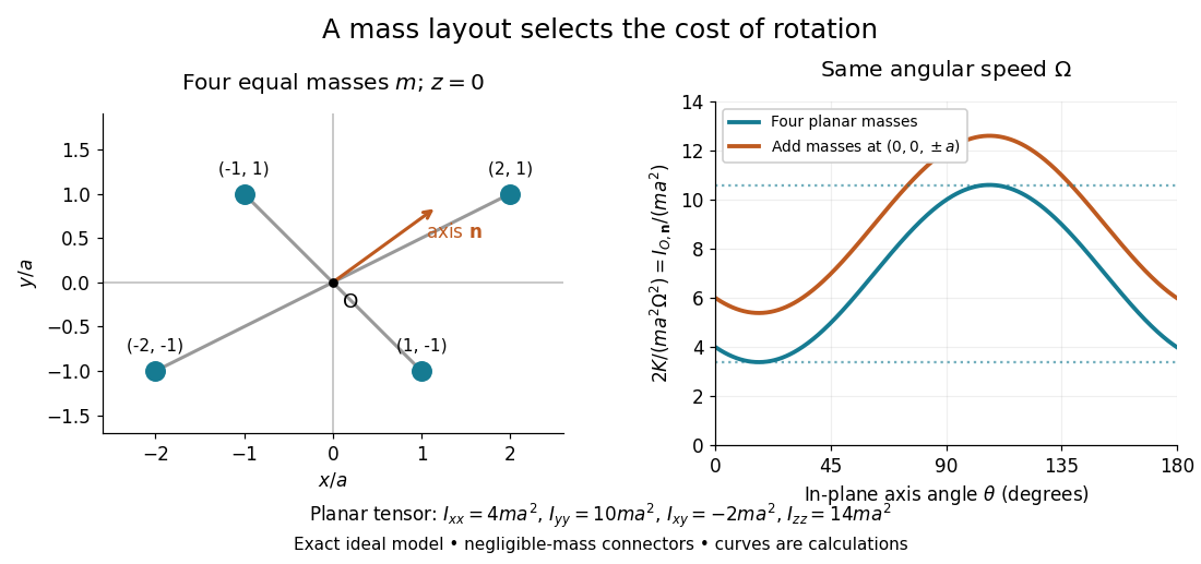
Paired point masses and direction-dependent rotational kinetic energy
. Original exact model. Four equal point masses lie in the plane with negligible-mass connectors. The curves use angular velocity and plot . Adding two more equal point masses at raises this curve by two. Markers depict ideal point masses, not finite-sized weights; no experimental data are plotted. Details.
For an in-plane unit vector , the planar model hasIts extrema are the principal moments of inertia and ; the remaining principal moment of inertia is . These values follow from the two-by-two characteristic polynomial , so they can be checked without trusting a numerical eigenvalue routine. At a stipulated angular speed , with and , rotation about , or has rotational kinetic energy , or , respectively.
A truly three-dimensional example adds two more equal point masses at and . Each contributes to the inertia tensor, givingThe in-plane principal axes stay the same while their principal moments of inertia each increase by . The moment of inertia stays unchanged because the added point masses lie on that axis. This comparison changes the total mass from to ; it holds the original four point masses fixed rather than redistributing a fixed total mass.
PASCO's PASPORT Rotary Motion Sensor Experiment Guide, Experiment 1, specifies a PS-2120A sensor, a rod carrying two equal-radius weights, a three-step drive wheel, a thread and hanging mass, a clamp-on guide wheel, a support, a balance and calipers. The thread leaves the drive wheel tangentially. The sensor records angular velocity against time; a linear regression over the accelerating interval supplies angular acceleration . The guide measures the drive radius with calipers and repeats the run with the weights removed to subtract the apparatus's own moment of inertia. Its tables are blank: it prescribes a measurement and does not report an observed numerical agreement. [ref]
With hanging mass including its hanger, effective drive radius , no thread slip and negligible guide-wheel inertia, Newton's second law gives thread tension . The axial torque is . Under negligible friction, the inference is thereforeRepeat the inference for the unloaded assembly and subtract: . Omitting the term incorrectly treats thread tension as the hanging weight. Comparing with tests the point mass approximation; finite-sized weights also have their own moments of inertia about their centres of mass. [ref]
Useful proposed checks go beyond that ideal inference. Verify the rotary encoder's angle scale by turning the shaft through a marked full revolution; check the recorded time against an independent clock and the balance against a known mass. Measure at the thread's running surface, including thread thickness; avoid overlapping wraps that change . Release without a push, inspect the angular velocity record for a straight interval, and stop before the hanger lands or the thread runs out. Repeat with several hanging masses, weight radii and rotation directions. A consistent inferred moment of inertia across drive torques supports the model; curvature, direction dependence or drift indicates a limitation rather than a new principal moment of inertia.
For approximately constant resisting torque in one rotation direction, an original calibration model isFit the left-hand quantity against across several drives: the slope estimates the axial moment of inertia and the intercept estimates . This calibration is conditional on friction remaining constant over the fitted angular speeds; a freely slowing run can expose speed dependence. Sensor differentiation noise, guide-wheel moment of inertia, thread slip, flexing connectors and uncertain weight radii limit the inference. Removing weights can also change bearing loads, so empty-apparatus subtraction does not automatically cancel friction. These are proposed controls and a model extension, not results claimed by PASCO.
A fixed-axis readout measures , not the full inertia tensor. In a proposed generalization, repeat about , , and the three diagonal directions , , , all through the same . For example,Six independent scalar readings then determine the six entries of a symmetric matrix. Each mounting needs its own apparatus correction, and different reference points require the tensor parallel-axis theorem before the readings can be combined.
A rotary encoder converts shaft rotation into a readout of angle or changes in angle. The PS-2120A uses interruptions of a light beam to encode shaft motion; its product specification gives 4000 divisions per revolution. That count is a resolution specification, not a guarantee of the precision of an inferred angular acceleration or moment of inertia. [ref]
If is the center of mass and , expanding the defining inertia tensor about gives the displayed formula. The cross terms vanish because in coordinates centred at . Contracting with a unit axis gives the parallel axis theorem, with the squared distance between the parallel axes equal to .
The principal moments of inertia about a specified point are the eigenvalues of the inertia tensor . Their associated unit vectors that are eigenvectors specify principal axes through . The spectral theorem for real symmetric matrices guarantees an orthonormal basis of these eigenvectors, even for an irregular rigid body. Choose their signs to make a right-handed basis and collect them as the columns of an orthogonal matrix :Thus diagonalization removes the off-diagonal coupling in the rotational kinetic energy. The eigenvalues belong to the mass distribution and reference point, independently of which orthonormal basis initially describes them. [ref]
In this principal body frame, write angular velocity as . ThenUse these as total angular momentum and kinetic energy only under the reference-point conditions stated under inertia tensor. Along a single principal axis with , angular momentum is parallel to angular velocity. For a mixture of directions with different principal moments of inertia, it generally is not. A principal axis need not be a geometric symmetry axis: it is selected by the complete mass distribution. A principal axis also need not give stable free rotation; for three distinct principal moments of inertia, the intermediate axis theorem supplies the stability distinction.
For any unit vector ,The axial moment of inertia is a weighted average of the principal moments of inertia. At fixed angular speed, the least and greatest rotational kinetic energies occur in the corresponding eigenspaces. At fixed nonzero angular momentum magnitude , instead, , so the largest principal moment of inertia gives the smallest rotational kinetic energy. These comparisons hold the reference point fixed.
There is an additional physical restriction beyond positive semidefiniteness. In principal axes coordinates,with two analogous cyclic inequalities. Therefore three arbitrary positive numbers do not always represent a possible inertia tensor. For a distribution in the plane through , , as in the planar inertia tensor of paired point masses. A uniform solid ellipsoid of mass and semiaxes supplies a continuous three-dimensional example: using its mass second-moment tensor, its central principal moments of inertia are , , . Setting recovers the moment of inertia of a uniform solid sphere.
For strictly positive principal moments of inertia and a fixed rotational kinetic energy , the allowed angular velocity components form an ellipsoid:Its semiaxis lengths have units of angular speed. The longest semiaxis corresponds to the smallest principal moment of inertia: that direction permits the greatest angular speed for the same rotational kinetic energy. This is a surface in angular velocity space, not the physical outline of the body. If one principal moment of inertia vanishes in an ideal line-mass model, this constant-energy surface is unbounded in that direction and is no longer an ellipsoid.
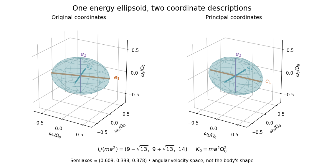

The rotational energy ellipsoid gives the geometry behind Poinsot's ellipsoid, but a constant-energy surface alone does not determine a free-rotation trajectory. A torque-free trajectory must also satisfy the conserved angular momentum constraint and the Euler equations for a torque-free rigid body.
If two principal moments of inertia coincide, for example , every direction in their two-dimensional eigenspace is a principal axis. The perpendicular axis is determined, but there is no privileged orthogonal pair within that plane. Rotating the pair in the plane leaves the diagonal inertia tensor unchanged. If all three principal moments of inertia coincide, and every axis through is principal. This follows from the eigenvalue multiplicity and eigenspace, rather than from a failure of diagonalization. [ref]
Equal principal moments of inertia do not prove that a body's outline has continuous rotational symmetry. For example, six equal point masses at , and have . This discrete layout has the same axial moment of inertia in every direction, although its actual mass distribution changes under most rotations. Conversely, even when all three principal moments of inertia are distinct, principal axes are unoriented lines: reversing an eigenvector's sign gives the same axis. Near repeated eigenvalues, small measurement errors can rotate fitted principal axes substantially within the nearly degenerate eigenspace, so quoted directions need an uncertainty assessment as well as quoted principal moments of inertia.
For torque-free rigid-body motion, the kinetic-energy ellipsoid fixed in the body rolls without slipping on the invariable plane perpendicular to the conserved angular momentum. Its point of contact is the angular-velocity vector.
The herpolhode is the contact curve traced on the fixed invariable plane in Poinsot's torque-free construction. It is distinct from the polhode, which is described in body coordinates.
Articles by others on the same topic
There are currently no matching articles.