Use orthonormal basis vectors fixed in the rotating reference frame, and expand the angular momentum as . Over time , the basis undergoes infinitesimal rotation , soThe product rule gives the rotating-frame derivative formula:Since the applied couple is the rate of change of angular momentum in the inertial frame,The second term accounts for the changing basis, even when the components of angular momentum are constant in the rotating reference frame.
One application is the slow steady precession of a rapidly spinning gyroscope supported at one point. Let its centre of mass be a distance from the pivot along its spin axis, at angle to the upward vertical. Write for its dominant spin angular momentum. In a reference frame precessing steadily about the vertical with angular velocity , the spin angular momentum is approximately stationary, soThe gravitational torque has magnitude . The cross product on the right has magnitude , giving, for a nonvertical axis,Its direction follows from the torque equation. This is the slow precession approximation: the additional angular momentum associated with precession is small compared with the spin contribution.
For this gyrocompass, let be local north, west and upward unit vectors, forming a right-handed basis. Earth's rotation has local componentsLet the spin axis point along , and write its dominant angular momentum as , where . In mechanical equilibrium relative to Earth, this leading angular momentum is fixed in the terrestrial rotating reference frame. The bearings can exert horizontal torques to keep the axle horizontal, but free rotation about the vertical implies . The vertical component of the rotating-frame derivative formula therefore requiresAway from either geographical pole, , henceThis is a necessary equilibrium condition; the next part distinguishes its stable and unstable spin orientations. The rapid-spin approximation neglects angular momentum terms of order compared with . At either pole the horizontal component of Earth's rotation vanishes, and this north-seeking mechanism gives no preferred horizontal direction. The paper explicitly excludes ; if latitude is signed, must likewise be excluded.
For the gyrocompass oscillation, use the same local basis and define about the stable orientation, with spin angular momentum directed north at . Because the vertical is perpendicular to the horizontal axle, the extra vertical angular momentum from the slow azimuthal motion is . To leading order in Earth's small angular velocity,A constant vertical contribution from Earth's rotation has zero terrestrial time derivative; the transverse terrestrial contributions affect the following equation only at order . Taking the vertical component of the torque equation givesThe terrestrial derivative of is horizontal, as is , so neither contributes to this component. Thus the small angle satisfies, using the small-angle approximation ,This is simple harmonic motion, , with positive squared angular frequency away from the poles. The approximation requires rapid spin, small angular displacement and negligible bearing friction. Near the opposite orientation, putting instead yields , which is unstable. Consequently, the paper's oscillation claim applies to the stable equilibrium, not both north--south spin directions. Without damping the ideal gyrocompass continues to oscillate rather than settling.
For a thin gyrocompass flywheel with rotational symmetry, the perpendicular axis theorem gives . This does not require the mass to be concentrated at the rim. Convert the specified spin to angular velocity and use one sidereal day for Earth's rotation:At the given latitude,The associated oscillation period is . This uses the stated neglect of the support assembly's contribution to the moment of inertia; a substantial additional vertical moment of inertia would lengthen the oscillation period.
The bending moment is the internal torque transmitted across a cut through an elastic beam, about the transverse bending axis. It balances the moments of the external forces on the isolated portion on one side of the cut. Its sign depends on the chosen convention, and its units are .
The relevant “moment of area” is the second moment of area of the cross-section about its neutral axis:where is perpendicular distance from that axis within the section. It has units and is a geometrical quantity, unlike a mass moment of inertia. For a homogeneous beam under pure bending, the neutral axis passes through the section's centroid, and its longitudinal strain is zero.
Assume a slender homogeneous elastic beam obeying linear elasticity, with plane sections remaining plane and no resultant longitudinal force. A length element of its neutral axis subtending a small angle has length . A neighbouring fibre at distance from that axis has a length change of magnitude , giving longitudinal strain with signs chosen consistently for tensile and compressed fibres. By Hooke's law, its longitudinal stress is .
The torque of these longitudinal forces about the neutral axis is thereforeHere is Young's modulus and the second moment of area. The displayed relation uses a signed radius and bending moment; an unsigned geometrical radius is . For consistency with the negative bending moments in the later parts, take the deflection positive downward and the signed curvature as . Then the small-slope Euler-Bernoulli beam equation reads . Reversing the vertical coordinate reverses the corresponding sign relation but leaves the physical deflection unchanged.
By vertical force balance and reflection symmetry, each support exerts an upward force . Use the paper's convention in which the sagging bending moment is negative. For a cut at , the left support's moment about that cut givesFor , include the central downward force when taking moments of all loads to the left:ThusThe bending moment is continuous at the load, with , and vanishes at both freely rotating supports. The jump is in its first derivative, reflecting the concentrated transverse force.
The uniform weight per unit length is , where is the mass density and the gravitational acceleration. The total weight is , so each support provides an upward force . The weight on the portion from to is acting at that portion's midpoint, a distance from the cut. In the same bending moment convention as part (c),The units are . Its greatest magnitude occurs at , where .
Take downward deflection positive, with the support level . The rectangular section second moment of area about the horizontal neutral axis isFor small slopes the curvature relation from part (b), with the stated sign convention, isIntegrating twice givesThe support boundary conditions give and . HenceThis is a downward displacement; its upward component is . As checks, reflection symmetry gives , and the maximum downward deflection isThe units are length: has units . The width cancels because both weight and bending resistance scale with it. The small-slope approximation requires ; shear strain is also neglected, as appropriate for a slender elastic beam.
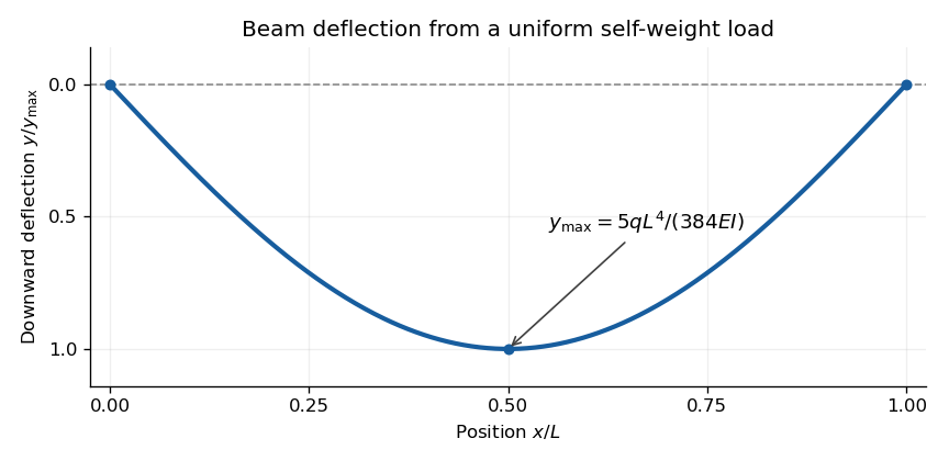
Calculated deflection of a simply supported beam under its own weight; downward displacement is positive
. Details. 
Articles by others on the same topic
There are currently no matching articles.