The transfer is a Hohmann transfer orbit. Write for the original circular Kepler orbit radius and for the transfer ellipse's semi-major axis. The diagram measures both radii from Earth's centre, giving , and henceThe Hohmann transfer time is half the transfer orbital period, taking the satellite to the opposite end of the elliptic orbit. By Kepler's third law, relative to the original geostationary orbit's orbital period ,Using one sidereal day, , gives ; the usual approximation gives . The arrival impulse changes the velocity into that of the new circular Kepler orbit without adding coast time in the impulsive model.
There is a real discrepancy between the wording and the diagram: an increase in altitude above Earth's surface is different from the radius increase drawn. If altitude is interpreted literally, let be Earth's radius. Thenusing and . Thus answers the explicitly labelled geometry; answers the literal altitude wording.
To find the two-mass three-spring normal modes, choose both displacements positive to the right, measured from mechanical equilibrium. The middle spring's extension changes by . Hooke's law and Newton's second law therefore giveIn a normal mode both displacements have the same angular frequency: take . A nonzero amplitude vector exists when the determinant vanishes:Writing , the two angular frequencies areThe corresponding eigenvectors can be specified bySince for positive masses, the lower normal mode has : both bodies move in the same direction at any instant. The higher normal mode has : they move in opposite directions. Their amplitudes are generally unequal. For the useful check , these reduce to with , and with . Each angular frequency has units .
An Electron has electric charge , so its gain of kinetic energy through an accelerating electric potential difference of magnitude is . Starting from rest, conservation of energy givesWith , electron mass , and ,This is a speed; the velocity points along the accelerating path, opposite the electric field. Here , where is the speed of light, so the classical kinetic energy approximation is accurate. As a check, special relativity gives and , agreeing to the quoted precision.
The quoted capacitance is that of the filled parallel-plate capacitor, . Disconnecting the source imposes charge conservation on the isolated plates:On removing the dielectric, the capacitance falls by its relative permittivity, so . The capacitor energy at fixed electric charge is . ThereforeandThe increase is supplied by the external work needed to withdraw the dielectric against its attraction into the electric field, in the lossless quasistatic limit. The final electric potential difference is , not the original charging value.
For the propagating mode of an air-filled or evacuated rectangular electromagnetic waveguide, the longitudinal dispersion relation isThe phase velocity and group velocity along the guide are consequentlyWith waveguide cutoff frequency and carrier frequency , . ThusThe pulse envelope travels at the group velocity for a sufficiently narrow range of frequencies. The phase velocity exceeding the speed of light does not describe superluminal signal transport. The check follows directly from the dispersion relation. A different uniform filling medium would require replacing by its electromagnetic propagation speed; the stated numerical answer uses the usual empty-guide assumption.
Use orthonormal basis vectors fixed in the rotating reference frame, and expand the angular momentum as . Over time , the basis undergoes infinitesimal rotation , soThe product rule gives the rotating-frame derivative formula:Since the applied couple is the rate of change of angular momentum in the inertial frame,The second term accounts for the changing basis, even when the components of angular momentum are constant in the rotating reference frame.
One application is the slow steady precession of a rapidly spinning gyroscope supported at one point. Let its centre of mass be a distance from the pivot along its spin axis, at angle to the upward vertical. Write for its dominant spin angular momentum. In a reference frame precessing steadily about the vertical with angular velocity , the spin angular momentum is approximately stationary, soThe gravitational torque has magnitude . The cross product on the right has magnitude , giving, for a nonvertical axis,Its direction follows from the torque equation. This is the slow precession approximation: the additional angular momentum associated with precession is small compared with the spin contribution.
For this gyrocompass, let be local north, west and upward unit vectors, forming a right-handed basis. Earth's rotation has local componentsLet the spin axis point along , and write its dominant angular momentum as , where . In mechanical equilibrium relative to Earth, this leading angular momentum is fixed in the terrestrial rotating reference frame. The bearings can exert horizontal torques to keep the axle horizontal, but free rotation about the vertical implies . The vertical component of the rotating-frame derivative formula therefore requiresAway from either geographical pole, , henceThis is a necessary equilibrium condition; the next part distinguishes its stable and unstable spin orientations. The rapid-spin approximation neglects angular momentum terms of order compared with . At either pole the horizontal component of Earth's rotation vanishes, and this north-seeking mechanism gives no preferred horizontal direction. The paper explicitly excludes ; if latitude is signed, must likewise be excluded.
For the gyrocompass oscillation, use the same local basis and define about the stable orientation, with spin angular momentum directed north at . Because the vertical is perpendicular to the horizontal axle, the extra vertical angular momentum from the slow azimuthal motion is . To leading order in Earth's small angular velocity,A constant vertical contribution from Earth's rotation has zero terrestrial time derivative; the transverse terrestrial contributions affect the following equation only at order . Taking the vertical component of the torque equation givesThe terrestrial derivative of is horizontal, as is , so neither contributes to this component. Thus the small angle satisfies, using the small-angle approximation ,This is simple harmonic motion, , with positive squared angular frequency away from the poles. The approximation requires rapid spin, small angular displacement and negligible bearing friction. Near the opposite orientation, putting instead yields , which is unstable. Consequently, the paper's oscillation claim applies to the stable equilibrium, not both north--south spin directions. Without damping the ideal gyrocompass continues to oscillate rather than settling.
For a thin gyrocompass flywheel with rotational symmetry, the perpendicular axis theorem gives . This does not require the mass to be concentrated at the rim. Convert the specified spin to angular velocity and use one sidereal day for Earth's rotation:At the given latitude,The associated oscillation period is . This uses the stated neglect of the support assembly's contribution to the moment of inertia; a substantial additional vertical moment of inertia would lengthen the oscillation period.
The bending moment is the internal torque transmitted across a cut through an elastic beam, about the transverse bending axis. It balances the moments of the external forces on the isolated portion on one side of the cut. Its sign depends on the chosen convention, and its units are .
The relevant “moment of area” is the second moment of area of the cross-section about its neutral axis:where is perpendicular distance from that axis within the section. It has units and is a geometrical quantity, unlike a mass moment of inertia. For a homogeneous beam under pure bending, the neutral axis passes through the section's centroid, and its longitudinal strain is zero.
Assume a slender homogeneous elastic beam obeying linear elasticity, with plane sections remaining plane and no resultant longitudinal force. A length element of its neutral axis subtending a small angle has length . A neighbouring fibre at distance from that axis has a length change of magnitude , giving longitudinal strain with signs chosen consistently for tensile and compressed fibres. By Hooke's law, its longitudinal stress is .
The torque of these longitudinal forces about the neutral axis is thereforeHere is Young's modulus and the second moment of area. The displayed relation uses a signed radius and bending moment; an unsigned geometrical radius is . For consistency with the negative bending moments in the later parts, take the deflection positive downward and the signed curvature as . Then the small-slope Euler-Bernoulli beam equation reads . Reversing the vertical coordinate reverses the corresponding sign relation but leaves the physical deflection unchanged.
By vertical force balance and reflection symmetry, each support exerts an upward force . Use the paper's convention in which the sagging bending moment is negative. For a cut at , the left support's moment about that cut givesFor , include the central downward force when taking moments of all loads to the left:ThusThe bending moment is continuous at the load, with , and vanishes at both freely rotating supports. The jump is in its first derivative, reflecting the concentrated transverse force.
The uniform weight per unit length is , where is the mass density and the gravitational acceleration. The total weight is , so each support provides an upward force . The weight on the portion from to is acting at that portion's midpoint, a distance from the cut. In the same bending moment convention as part (c),The units are . Its greatest magnitude occurs at , where .
Take downward deflection positive, with the support level . The rectangular section second moment of area about the horizontal neutral axis isFor small slopes the curvature relation from part (b), with the stated sign convention, isIntegrating twice givesThe support boundary conditions give and . HenceThis is a downward displacement; its upward component is . As checks, reflection symmetry gives , and the maximum downward deflection isThe units are length: has units . The width cancels because both weight and bending resistance scale with it. The small-slope approximation requires ; shear strain is also neglected, as appropriate for a slender elastic beam.
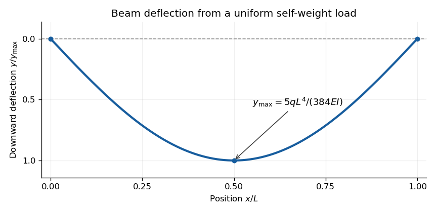
Calculated deflection of a simply supported beam under its own weight; downward displacement is positive
. Details. 
The Poynting vector is the local electromagnetic energy flux density:Here is the electric field and the magnetic field intensity. For an oriented area element , is the electromagnetic power crossing that element in its positive normal direction. Thus is outward power through a closed surface, in watts. The Poynting vector has units , and its direction describes local electromagnetic energy transport.
The unit relative permittivity and vacuum-valued magnetic permeability imply and . The electromagnetic energy per unit volume isThe two contributions are the stored electric and magnetic energies. Although called in this paper, this quantity is an energy density; the total electromagnetic energy is .
Use the divergence identity for a cross product, followed by Faraday's law of induction and the Ampère-Maxwell equation:With the electromagnetic energy density of part (b), these giveIntegrate over a fixed volume and apply the divergence theorem, choosing outward:This is Poynting's theorem. The outward electromagnetic energy flux equals minus the power transferred to matter and minus the rate at which electromagnetic energy accumulates inside. For the dissipative electrical conductor in this question, the matter term is Ohmic heating.
Take the electric current along , and use cylindrical coordinates. A uniform current in a straight homogeneous wire hasThe local Ohm's law gives the longitudinal electric fieldFor a circular Amperian loop of radius , the enclosed electric current is . The magnetostatic Ampère law gives , henceSince , the Poynting vector isIt is zero at the centre and points radially inward elsewhere. Its units are . These are the interior fields in the long-wire approximation, neglecting end and contact effects.
The Ohmic heating per unit volume is , uniform in this wire. Multiplying by its volume gives the dissipated powerwhere the electrical resistance is . The result is in watts; over a time interval the dissipated energy is .
On the curved wire surface, the outward normal is and the Poynting vector has the constant radial value . Its outward flux isThe Poynting vector is radial, so it has zero normal component on the two end faces in this approximation. This is therefore also the outward flux through the complete wire surface. Equivalently, positive electromagnetic power flows inward.
The fields are steady, so the stored electromagnetic energy does not change. Poynting's theorem consequently requires the incoming power to equal the Ohmic heating in part (e), exactly as found. The energy reaches the wire through the surrounding electromagnetic field. A local check is .
Let the unit normal point from material 1 to material 2, and let their relative magnetic permeabilities be , so for linear isotropic media. Apply Gauss's law for magnetism to an infinitesimal Gaussian pillbox straddling the interface. The side contribution vanishes as its height tends to zero, leavingThe normal magnetic flux density is continuous.
Next use a narrow rectangular Amperian loop crossing the interface. The two short-side contributions vanish in the zero-height limit. The magnetostatic Ampère law for magnetic field intensity giveswhere is any free surface current density. Thus, if there is no free surface current density on the interface, the tangential magnetic field intensity is continuous. In that case the component relations areThe distinction between free and bound electric currents matters: bound currents due to magnetization are already incorporated in the definition of magnetic field intensity. A change of magnetic permeability alone does not make the tangential magnetic flux density continuous.
The starting point is Gauss's law for magnetism, : a flux tube carries the same magnetic flux through successive transverse sections. To identify that tube approximately with the physical core, one must also make a negligible-leakage approximation. The large core magnetic permeability makes the core route much less reluctant than competing paths through the surrounding air; the small gap further reduces the incentive for a long external return path. The gentle taper, , lets the field follow the changing section with only small transverse corrections.
For two cuts and the intervening lateral surface, the divergence theorem gives . Neglecting lateral leakage givesThe normal magnetic flux density is continuous at each core–air interface by part (a), so this same magnetic flux crosses the gap. To use the gap's geometrical area in the later formulas, the magnetic fringing must also be negligible, normally requiring . This is the small-gap interpretation of the paper's approximation. Large magnetic permeability alone does not eliminate leakage or magnetic fringing for arbitrary gap geometry.
For the closed untapered torus, apply the magnetostatic Ampère law to a circular path through the core. It links all turns, each carrying electric current :Since , variation of the path length and of the tangential magnetic field intensity across the section is negligible. Thus , giving, within this thin-torus approximation,The units are . The core magnetic flux density is in the linear material model.
With uniform section and negligible magnetic fringing, constant magnetic flux gives equal magnetic flux densities in the core and gap:Here is the core arc length and the additional gap length. Applying the magnetostatic Ampère law around the complete magnetic circuit,Consequently,This tends to when the gap dominates the magnetic reluctance, , and reduces to the no-gap result as . The gap magnetic flux density is .
Let the approximately conserved magnetic flux be . ThenThe length shown in the original diagram is the untapered core arc; the two tapers are separate lengths each. In the untapered core, flux conservation givesFor one taper use distance from its narrow end. The straight taper in the diagram has local radiusand magnetic field intensityIts contribution to the line integral in the magnetostatic Ampère law is found explicitly:Adding the gap, the untapered arc and both tapers givesThereforeThis uses a linear radius profile, approximately uniform magnetic flux density over each section, a linear constant magnetic permeability, and negligible leakage and magnetic fringing. For a non-linear taper profile the honest generalization isThus an arbitrary smooth taper with the same end radii and length need not give the printed formula; the straight-sided geometry supplies the additional information.
Set . Comparing with the untapered expression in part (d), using the same and large radius ,The stated limit makes , soThe taper concentrates magnetic flux into a smaller pole-face area, increasing the gap magnetic field intensity and magnetic flux density for the same winding electric current. If , the enhancement approaches . If instead , the gap dominates the magnetic reluctance and the enhancement approaches unity: both fields approach .
The benefit is therefore strongest when the untapered core's contribution is significant, while the taper lengths contribute little. The same-core-length convention is the comparison defined by parts (d) and (e); if one instead fixes the full iron path length, the untapered comparator has length , a difference negligible in the stated limit. A smaller gap area can increase the field even though the total magnetic flux need not increase. Magnetic saturation and magnetic fringing, excluded from this model, limit the ideal concentration.
Articles by others on the same topic
There are currently no matching articles.