Photography records a spatial distribution of light as an image. An optical lens or optical pinhole establishes a correspondence between scene directions and positions on a receiving surface; a photographic emulsion or photodetector preserves the resulting signal. Image formation and recording are separate parts of the process.
This makes photography useful for scientific measurement: a photograph can preserve the geometry of a nuclear emulsion track or the changing appearance of an astronomical source. Interpreting the record still requires calibration. Image brightness depends on the instrument and the duration of illumination as well as on the source, and a visible feature's width can reflect the point spread function rather than the object's physical diameter.
Stereoscopy uses images from different viewpoints to convey or recover depth. In scientific photography, identifying the same feature in two calibrated views permits stereoscopic triangulation: intersecting the directions inferred from the two images.[ref]
What Is Stereo Reconstruction? by MathWorks. How Does Stereo Reconstruction Work? and Stereo Camera Calibration
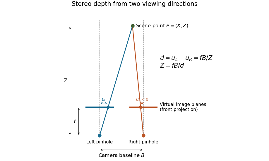
Consider ideal cameras with parallel axes, separated by a baseline . With matching forward-projection coordinates and common focal length in image-coordinate units, a point at projects toSubtracting gives the stereo disparity , hence . If and are measured in pixels, has the same length unit as .
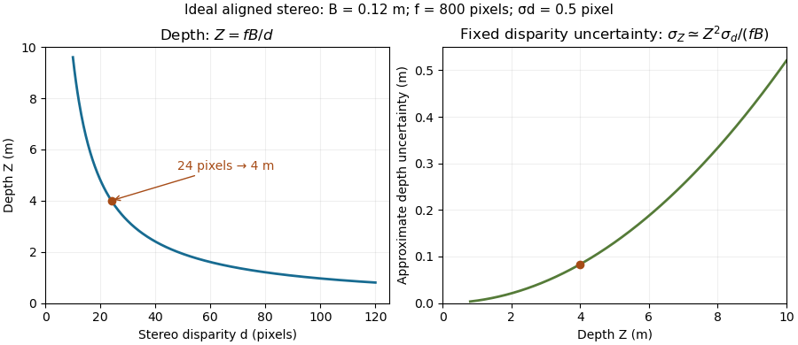
For an original example, , pixels and pixels give . First-order propagation of uncertainty gives . Thus fixed disparity precision produces increasing depth uncertainty for more distant objects. Correctly matching the same feature is also essential; ambiguous or hidden features can defeat the reconstruction even when the geometry is known.
Epipolar geometry describes the projective relationship between two camera views. A scene point away from the camera baseline and the two camera centers determine an epipolar plane. Its intersections with the image planes are corresponding epipolar lines. Knowing one image point therefore constrains its partner to a line rather than the whole second image.[ref]
Epipolar Geometry in the OpenCV-Python tutorials. Basic Concepts, two-camera plane and epipolar constraint
With image points in homogeneous coordinates, a fundamental matrix expresses the constraintFor an ideal horizontally rectified pair this reduces to equality of image-row coordinates, while horizontal displacement remains free and carries stereo disparity. A line constraint does not determine depth: many scene points along one viewing ray satisfy the geometry. Correct stereo correspondence selects a partner, and camera calibration then supports metric stereoscopic triangulation.
The fundamental matrix encodes the epipolar geometry of two distinct camera centers using image homogeneous coordinates. For matching image points , the ideal constraint isThus is an epipolar line in the right image, while is an epipolar line in the left image. A nondegenerate fundamental matrix has matrix rank two and is defined only up to nonzero scale.[ref]
Epipolar Geometry in the OpenCV-Python tutorials. Basic Concepts: correspondence constraint, rank-two matrix and point-to-line mapping
For an ideal horizontally aligned stereo pair with matched image coordinate origins, one possible scale convention isPutting gives , so the right point must satisfy . Its horizontal coordinate remains free: the constraint reduces the search to a line but does not determine stereo disparity or depth. Repeated texture can still make stereo correspondence ambiguous.
With camera calibration matrices and relative pose under the convention , the relation is , where . Translation direction affects the geometry, but multiplying by a scalar only rescales : the fundamental matrix alone cannot establish a metric camera baseline. Pure rotation has and requires a different geometric description.[ref]
Epipolar Geometry in the OpenCV-Python tutorials. Basic Concepts: essential and fundamental matrices, intrinsic calibration and degrees of freedom
An epipolar plane contains both camera centers and a scene point. For a scene point away from the camera baseline, these three points determine a unique plane. Its intersection with each image plane is an epipolar line, so corresponding image points lie on the two traces of the same plane.[ref]
Epipolar Geometry in the OpenCV-Python tutorials. Basic Concepts, diagram of the baseline, scene point and epipolar plane
To see the geometry directly, take camera centers and , and a scene point . The plane they span satisfies . For parallel forward-facing image planes at common focal length , its traces have in both views. This is why an ideal horizontal stereo pair places corresponding image points on the same row.
Moving the scene point within that plane leaves its epipolar lines unchanged. A single trace therefore cannot recover depth. If the scene point lies on the baseline, the three defining points are collinear and no unique epipolar plane is determined. These degeneracies explain both the usefulness and the limits of line-based stereo correspondence.
An epipolar line is the image-plane trace of an epipolar plane. Given one point in the first camera image, the partner of that scene point must lie on the corresponding epipolar line in the other view. A fundamental matrix maps the first point to coefficients of that line.[ref]
Epipolar Geometry in the OpenCV-Python tutorials. Basic Concepts, point-to-line mapping and computeCorrespondEpilines example
For example, let andThen , so a candidate satisfies . The partner can have different horizontal coordinate , but must lie on row 50 in this ideal model. Intersecting candidate matches with this line reduces the search; it does not resolve repeated textures or guarantee that a visible partner exists.
Stereo correspondence identifies image positions in two views that depict the same scene point. This is the matching step needed before stereoscopic triangulation can recover that point. Epipolar geometry restricts a candidate match to an epipolar line; after horizontal stereo rectification, that search follows a corresponding image row.[ref]
What Is Stereo Reconstruction? by MathWorks. How Does Stereo Reconstruction Work?; Epipolar Geometry and Camera Rectification
For example, matching a corner at horizontal coordinate 120 in the left view with coordinate 96 in the right gives stereo disparity 24 pixels. A repeated window pattern might offer equally plausible candidates at 96 and 72, producing different inferred depths. Geometry alone does not choose the correct window. A foreground object can also hide the feature in one view: occlusion in stereo vision then prevents a visible match. Texture, agreement of nearby matches and explicit rejection of ambiguous locations supply evidence beyond mere proximity along a row. A confident disparity map must represent locations where stereo correspondence failed as well as those where it succeeded.
Occlusion in stereo vision occurs when a scene feature visible from one camera is hidden behind another surface from the second viewpoint. Such a feature has no visible partner, even if camera calibration is exact. Stereo correspondence must allow unmatched locations instead of forcing every image location to have a partner.[ref]
Disparity map post-filtering in the OpenCV documentation. Introduction, half-occlusions, depth discontinuities and invalidating inaccurate disparities
Consider a nearby post in front of a distant wall. Moving the viewpoint sideways shifts the post's projection more than the wall's because their depths differ. A strip of wall exposed beside the post in one image can therefore be covered in the other. Matching that strip to the post invents a depth belonging to the wrong surface. Missing-value masks and consistency checks can help represent this limitation, while smoothing a disparity map across the boundary can conceal it rather than recover the hidden wall.
Stereo rectification transforms a pair of images so that corresponding epipolar lines become aligned scan lines. In a horizontal stereo arrangement, a scene point visible in both rectified views should have the same vertical image coordinate. This turns a two-dimensional matching search into a one-dimensional search along a row.[ref]
Camera Calibration and 3D Reconstruction by OpenCV. stereoRectify(), horizontal stereo case, R1/R2 and P1/P2
For example, a feature initially at left row 100 and right row 104 can be mapped to the same row in virtual aligned views. Camera calibration supplies geometry for the transforms, and image resampling evaluates the transformed images on a new pixel grid. The new images need not retain every border region. Stereo rectification aligns the geometric search; it does not identify the correct partner among repeated patterns or restore a feature hidden in one view. The rectified focal length and coordinate offsets must also be used when converting stereo disparity to depth.
The camera baseline is the separation between the camera centers of two views. For centers , its length is . It measures translation, so turning a stationary camera without moving its camera center does not create a nonzero camera baseline. A known camera baseline supplies the length scale in stereoscopic triangulation.[ref]
What Is Stereo Reconstruction? by MathWorks. opening baseline definition and How Does Stereo Reconstruction Work?
In the ideal aligned model with matched coordinate origins, stereo disparity satisfies . For focal length 800 pixels and depth 5 metres, a camera baseline 0.10 metres gives 16 pixels; doubling the camera baseline gives 32 pixels. With unchanged disparity precision, the larger separation improves depth sensitivity. It can also increase occlusion in stereo vision and reduce overlap of the views. Finally, multiplying both and all reconstructed lengths by the same factor leaves the projections unchanged: a small reprojection error alone cannot certify the metric scale.
Stereoscopic triangulation reconstructs a scene point from corresponding image positions and known camera geometry. Each image position determines a viewing direction. Two correctly matched views constrain the point to lie on both viewing rays; one view alone leaves its position along a ray undetermined.
For an ideal aligned pair, put the left camera at the origin and the right one at in a Cartesian coordinate system, with their axes pointing in the positive direction. Assume a common focal length , square pixels, corrected distortion and image coordinates measured from aligned principal points. Forward perspective projection givesThe stereo disparity therefore determines all three coordinates:Here is depth along the camera axis; the Euclidean distance from the left camera is instead . If use pixels and the camera baseline uses metres, the recovered coordinates use metres. Without a known length scale, the images alone do not determine metric size.[ref]
Camera Calibration and 3D Reconstruction by OpenCV. Detailed Description, camera intrinsic matrix and the distortion-free pinhole projection equations
Real cameras require calibration before these simplified equations apply. Stereo rectification transforms the images to an aligned geometry. With noisy measurements, viewing rays need not intersect exactly; minimizing reprojection error instead seeks a point whose projected positions agree as closely as possible with the observations. Reconstruction also depends on stereo correspondence: a mathematically precise intersection of mismatched viewing directions can still describe the wrong scene point.[ref]
What Is Stereo Reconstruction? by MathWorks. Stereo Camera Calibration; Stereo Image Rectification; Disparity Map Computation; 3-D Scene Reconstruction
A reprojection error compares an observed image point with the position predicted by projecting a reconstructed scene point through a camera model. If is an observed position and its prediction, the residual is . One possible aggregate is the per-point root mean square Euclidean norm:Coordinates in pixels give an error in pixels. Least squares instead minimizes the associated sum of squares; normalization conventions should be stated when reporting a summary.[ref]
Camera Calibration in the OpenCV-Python tutorials. Re-projection Error, projecting known points and comparing image positions
For an observation and prediction , the Euclidean norm of the residual is 5 pixels. Camera calibration can adjust model parameters to reduce many such residuals, while stereoscopic triangulation can adjust a reconstructed point with the camera parameters fixed. Low reprojection error tests agreement with observations under that model; incorrect stereo correspondence or an incorrect camera baseline can still produce wrong scene geometry.
Stereo disparity is the difference between the image positions of the same scene feature in two views. For an ideal horizontally aligned pair, use signed horizontal coordinates with matched principal points and defineWith the orientation and camera baseline convention of stereoscopic triangulation, a point in front of the cameras has : stereo disparity measures inverse depth, rather than depth itself. Halving doubles when the camera baseline and focal length stay fixed.
A disparity map assigns this difference to matched image locations. Finding the matches is a separate stereo correspondence problem. A repeated pattern can give several plausible matches; a feature hidden from one camera has no visible partner. A small measured stereo disparity is therefore not, by itself, proof of a distant object: the match and calibration must also be credible.[ref]
What Is Stereo Reconstruction? by MathWorks. Stereo Image Rectification and Disparity Map Computation: aligned rows, matching pixels and disparity-to-depth conversion
The ideal relation also explains why far-away reconstruction becomes sensitive to measurement error. Differentiating gives ; the first-order propagation of uncertainty is . Thus equal disparity errors produce larger depth errors at greater depth. The example and curves under stereoscopy quantify this effect.
A disparity map assigns an estimated stereo disparity to image locations having accepted matches in another view. For a horizontally rectified pair, a left-image map can storewhere is the matching right-image horizontal coordinate. Constructing the map therefore requires stereo correspondence, rather than only reading individual pixel intensities. OpenCV's tutorial demonstrates block matching and shows how weak texture and spurious matches affect the result.[ref]
Depth Map from Stereo Images in the OpenCV-Python tutorials. Code; disparity image; texture_threshold, speckle and uniqueness filters
For matched coordinate origins, focal length 800 pixels and camera baseline 0.12 metres, valid disparities 20 and 40 pixels imply depths 4.8 and 2.4 metres. Thus a disparity map is not itself a metric depth map: its values must be interpreted using the calibrated geometry and representation. Rejected matches need an explicit validity convention. A displayed dark patch can mean an unavailable match rather than an infinitely distant surface, and an encoded invalid value must not be blindly substituted into .
A camera combines an image-forming arrangement with a surface that records the incident light. An optical lens collects many light rays from each object point and directs them toward a corresponding image point; a photographic emulsion or photodetector then records the image. The optical camera is the imaging part of this arrangement.
The simplest demonstration replaces the optical lens with an optical pinhole. In NASA's two-card activity, foil containing a small hole covers a window in one card, and a second white card receives the projected image of the Sun. Increasing the separation enlarges the image; making several holes produces several images. The receiving card is viewed from the side, rather than looking through the hole at the Sun.[ref]
An optical pinhole selects narrow bundles of light rays without refraction. A finite hole also produces geometric blur, and an extremely small hole makes diffraction important. These competing effects explain why reducing the hole indefinitely does not produce unlimited spatial resolution.
The camera center is the center of projection in an ideal perspective camera model: the common origin of its viewing rays. It is a point in scene space, distinct from a principal point, which is an image-plane coordinate. Two distinct camera centers define the camera baseline used by stereoscopy.
For the calibrated perspective projection model , where is a rotation matrix, the camera center satisfies . HenceThis follows by applying the inverse rotation to the zero camera-space position.[ref]
Camera Calibration and 3D Reconstruction by OpenCV. Detailed Description, world-to-camera transform and projection equations
For and metres, metres: the translation parameter is not directly the world-space camera center. Rotating about that center changes viewing directions without creating a new triangulation baseline.A photographic emulsion is a coating that responds to light to record an image in photography, for example on a photographic plate. Silver halide crystals, commonly silver bromide, are dispersed in gelatin. Exposure leaves a latent image. A developer produces dark silver grains and fixing removes remaining sensitive material. A microscope can reveal a charged particle's path through the coating: the basis of nuclear emulsion particle detection.[ref]
Research Profile: Cecil Powell by Luisa Bonolis. Luisa Bonolis, Research Profile: Cecil Powell, “A new visual method: nuclear emulsions”, paragraphs describing composition, coating, development, fixing and microscope observation
A latent image is the pattern of exposure-induced changes in a photographic emulsion before photographic processing makes it visible. A missing visible mark before development therefore says nothing about whether a charged particle passed through the coating.
A developed grain is a visible deposit of silver produced during photographic processing. The chain of developed grains in a nuclear emulsion records interactions along a charged particle's path. Its width is a property of the recording and viewing process, not a measurement of the particle's diameter.
A nuclear emulsion is a photographic emulsion prepared for recording charged particles. The sensitive material serves as both target and record: a particle may slow, stop, decay or cause a nuclear reaction inside it. Reading that record requires track reconstruction, not recognizing a miniature picture of a particle. Unlike a cloud chamber photograph, the exposed nuclear emulsion itself retains the record until it is developed and examined.
In 1947, Cesare Lattes, Hugh Muirhead, Giuseppe Occhialini and Cecil Frank Powell reported charged particle tracks in which a stopping particle was followed by a secondary particle. Their paper treated the interpretation as provisional.[ref]
Processes Involving Charged Mesons by Cesare Mansueto Giulio Lattes and others. Lattes, Muirhead, Occhialini and Powell, Processes Involving Charged Mesons, Nature 159 (24 May 1947), pp. 694–697, abstract and byline
The eventual distinction between pions and muons made a striking use of photography: a tiny permanent record could distinguish particles by how they slowed and transformed.The method already had a history. In their jointly authored 1937 report, Marietta Blau and Hertha Wambacher described photographic plates exposed for five months at Hafelekar, above sea level.[ref]
Disintegration Processes by Cosmic Rays with the Simultaneous Emission of Several Heavy Particles by Marietta Blau and Hertha Wambacher. Blau and Wambacher, Disintegration Processes by Cosmic Rays with the Simultaneous Emission of Several Heavy Particles, Nature 140 (1937), p. 585, opening paragraph and joint byline
Neither shared the 1950 Nobel Prize in Physics, awarded to Cecil Frank Powell.[ref]Research Profile: Cecil Powell by Luisa Bonolis. Opening award statement: Powell's 1950 prize concerned development of the method and meson discoveries
This was a development of photographic particle detection, with earlier contributors, rather than its invention by one person.In his own later account, Cesare Lattes recalls calibrating emulsion shrinkage and the particle range–energy relation with accelerator-produced particles. Giuseppe Occhialini took borax-treated and untreated plates to Pic du Midi for about a month. The untreated plates provided a control; the treated plates retained more events because latent image fading was reduced. Later, Cesare Lattes exposed plates at the higher Chacaltaya station in Bolivia and obtained more candidate events.[ref]
Meu Trabalho em Física de Mésons com Emulsões Nucleares by Cesare Mansueto Giulio Lattes. Lattes, Meu trabalho em física de mésons com emulsões nucleares, 1984 recollection in Portuguese translation, paragraphs beginning “Foi-me dada a tarefa”, “Occhialini e eu decidimos”, “Quando Occhialini revelou” and “Assim, propus”; the recollection's altitude estimate is not adopted here
The Pic du Midi cosmic ray exposure was roughly above sea level.[ref]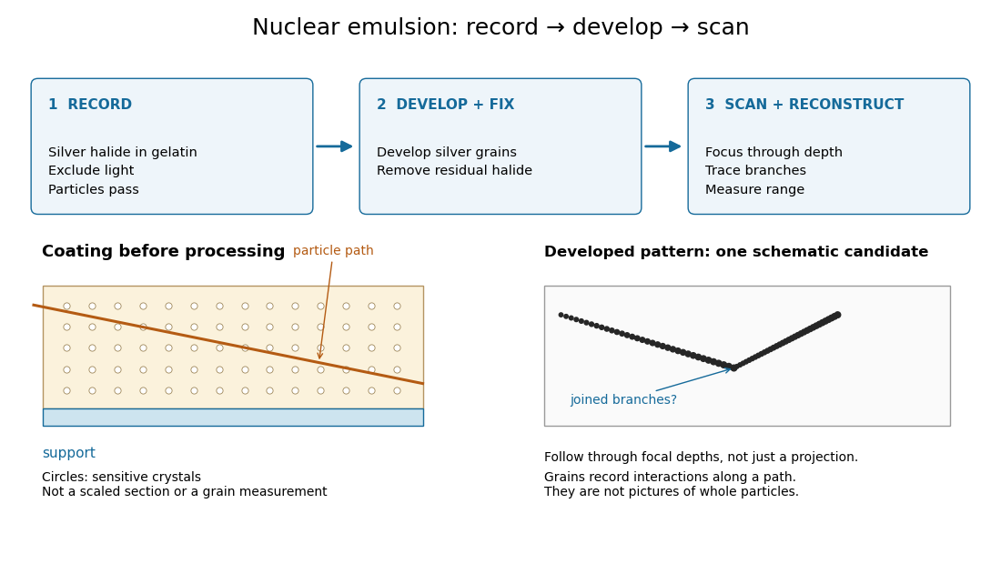
An emulsion range measurement follows a stopping charged particle through the coating to estimate its complete particle range. A projected length on one image can underestimate the distance travelled. In an original geometry example, a straight segment with projected length and corrected depth change has lengthUsing the projection alone would underestimate this length by . A bent track requires a sum over reconstructed segments. These are stipulated coordinates, not measurements of a historical track.
Suppose photographic processing contracts the coating only in depth, with shrinkage ratio . Then an observed depth difference corresponds to . For , an observed becomes the used above. This correction assumes uniform contraction and unchanged lateral dimensions; it cannot repair a track that leaves the coating before stopping.
A simple continuous-loss model connects particle range to kinetic energy through stopping power :This describes the mean trend for a specified particle and material. Fluctuating energy loss produces a spread of stopping distances, called range straggling. An exit point supplies only a lower bound on particle range. Consequently, a narrow distribution from fully contained tracks and one assembled by treating exits as stops answer different questions.
Range straggling is the event-to-event spread in particle range for otherwise similar incident particles, caused by fluctuations in their energy loss and transport through matter. It must be distinguished from measurement uncertainty and from the incomplete recording of particles that escape.
The track grain density is the number of resolved developed grains along reconstructed track length , divided by . It is a response variable, not a universal conversion from darkness to energy. Overlapping developed grains, exposure fading, processing and optical spatial resolution can all change what is counted. Calibration must use comparable material and viewing conditions.
Cesare Lattes specifically recalls distinguishing meson tracks from proton tracks using their greater deflection by scattering and changing track grain density toward the stopping point. He also recounts a secondary track that left the coating, requiring extrapolation rather than a directly measured stopping distance.[ref]
Meu Trabalho em Física de Mésons com Emulsões Nucleares by Cesare Mansueto Giulio Lattes. 1984 recollection, paragraph beginning “Devo adicionar”: scattering, grain density and an escaping secondary; no numerical grain count is reported here
For a candidate joined track, the useful questions are whether both branches actually meet in depth, whether the incoming branch is consistent with stopping there, and whether the outgoing branch has the expected particle range and track grain density. A visible change of direction alone cannot distinguish a decay from scattering or an accidental crossing. Examining successive focal depths tests a projected crossing; comparison with ordinary stopping tracks tests the identification. These are measurement checks, not a claim that the original plates provided time-resolved movies.
A nuclear emulsion integrates exposure over time. It does not by itself supply the time between two apparently joined branches. Finite spatial resolution also limits how tightly one can establish their common origin: developed marks and the microscope response are much larger than a subatomic particle. There is no single resolution number applicable to every emulsion, developer and optical arrangement.
Cecil Frank Powell's 1950 lecture illustrates the successive decays of pions and muons through their tracks and explains why the nearly fixed secondary muon range, allowing for range straggling, supports a single neutral decay partner. He describes its identification as a neutrino tentatively. The neutral particle itself leaves no recorded track. He contrasts this decay with the nuclear reactions caused by stopped negative pions, connecting the latter with the nuclear force.[ref]
Here is a modern special relativity derivation for the dominant leptonic pion decay, assuming a free pion at rest, a massless muon neutrino, and no emitted photon. Write and for the pion and muon masses. By conservation of momentum the daughter momenta are opposite with equal magnitude . By conservation of energy and the energy–momentum relation,Substitute , square, and cancel . This givesThe resulting is fixed, although the muon's direction is not set by the incoming stopping track. Thus the kink angle relative to that earlier track is not the angle between the two daughters: in the pion rest frame, the daughters are back to back. A neutral-partner arrow in a diagram represents inferred momentum, not an observed string of grains.
For an original calculation, adopt rounded input values and . They give , and . Their sum satisfies . These are rounded calculation inputs and outputs, not a fit to the 1947 plates.
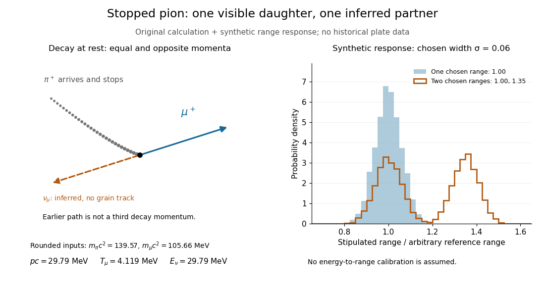
At fixed material and particle identity, a fixed initial kinetic energy suggests a narrow particle range distribution broadened by range straggling and measurement uncertainty. The synthetic example convolves a single chosen range with a normal distribution; a second example superposes two such chosen ranges. It explains why repeated comparable stopping distances can be informative, without pretending to extract a historical spectrum.
The decay equations do not identify the neutral partner as a neutrino on their own: a massless photon would satisfy the same energy and momentum equations. Nor does any isolated kink establish the pion's identity. The inference gains force from calibrated particle range, track grain density, repeated decay patterns and independent particle properties. Historical particle names should not obscure the distinction: a muon is a lepton, whereas a pion is a meson.
In photography, photographic processing uses chemical reactions to develop and stabilize an exposed photographic emulsion.
A photographer credited on Wikimedia Commons for the 2015 photograph of Martin Fowler embedded above. The attribution and exact photograph identity are given by the [ref]
https://commons.wikimedia.org/wiki/File:Webysther_20150414193208_-_Martin_Fowler.jpg. Commons file record
.Photographer credited by the Oberwolfach Photo Collection and the verified Wikimedia Commons file for the 2007 portrait displayed in James R. Norris. The credit is retained without adding unverified biographical details.
A photographer credited by Wikimedia Commons for the circa-1900 portrait of Carl Wernicke reproduced here.