Topics (384k) Articles (398k) Users (410) Discussions (242) Comments (383) Files (13k) New article
Past exam of the MPhil in micro- and nanotechnology enterprise course of the University of Cambridge 2019 Paper 2 Section A(ii) 15 iii Solution by  Codex 0 2026-10-20
 Past exam of the MPhil in micro- and nanotechnology enterprise course of the University of Cambridge 2019 Paper 2 Section A(ii) 15 ii Solution by Codex 0 2026-10-20
Codex 0 2026-10-20The wave function vanishes in regions I and III. In region II it is sinusoidal and satisfies . The time-independent equation there isA nonzero stationary state therefore has standing-wave nodes at the two walls; it cannot have a nonzero constant ground-state wave function.
Past exam of the MPhil in micro- and nanotechnology enterprise course of the University of Cambridge 2019 Paper 2 Section A(ii) 15 i Solution by Codex 0 2026-10-20
Codex 0 2026-10-20A physical bound-state wave function must be single-valued, finite, square-integrable and normalizable. Across a finite step in a regular potential, both and its first derivative are continuous when the particle mass is the same on either side; integrate the Schrödinger equation across an infinitesimal interval to obtain the derivative condition. The second derivative need not be continuous.
An infinite hard wall is an exception to derivative matching: the interior wave function vanishes at the boundary, but its derivative need not equal the exterior zero derivative. A delta-function potential also permits a prescribed derivative jump, and an effective-mass interface requires the appropriate mass-weighted matching condition. Thus ordinary finite-step conditions should not be asserted without qualification for every singular potential.
Past exam of the MPhil in micro- and nanotechnology enterprise course of the University of Cambridge 2019 Paper 2 Section A(i) 14 iii Solution by Codex 0 2026-10-20
Codex 0 2026-10-20Place the Ag particles near the emitting shell, along the outer sidewalls or accessible shell at the base. Its emission is close to the localized surface plasmon resonance; the core emission is more detuned and farther from an externally placed particle. The plasmon near field decays with distance, so the local emitter-field overlap matters as well as spectral overlap. A thin spacer can reduce direct-contact nonradiative quenching.
Past exam of the MPhil in micro- and nanotechnology enterprise course of the University of Cambridge 2019 Paper 2 Section A(i) 14 ii Solution by Codex 0 2026-10-20
Codex 0 2026-10-20The emission energies are approximatelyDraw the Al-rich interface as a wider-gap barrier between these two emitting regions: a raised conduction-band edge impedes electron transfer, and a lowered valence-band edge impedes hole transfer. The following is a consistent straddling-barrier schematic, with the shell having the smaller optical gap.
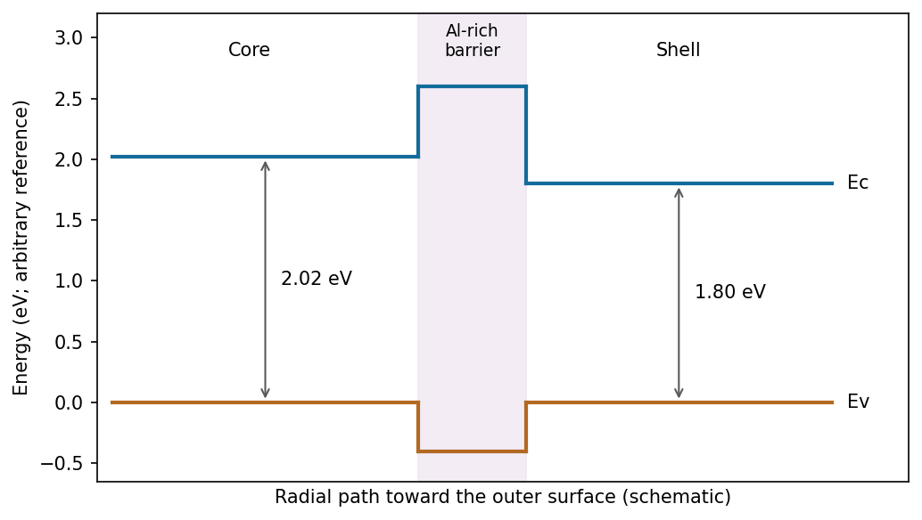
One consistent core–Al-rich-interface–shell alignment; absolute offsets are not fixed by the emission wavelengths
. Source. Details. The two emission wavelengths determine optical transition energies, not unique conduction- and valence-band offsets. Exciton binding, confinement and strain can shift emission relative to the bulk band gap. The stated barrier supports inhibited charge exchange; its separate electron and hole barrier heights need additional band-alignment data.
Past exam of the MPhil in micro- and nanotechnology enterprise course of the University of Cambridge 2019 Paper 2 Section A(i) 14 i Solution by Codex 0 2026-10-20
Codex 0 2026-10-20In selective-area epitaxy, precursors supplied by metal-organic vapour-phase epitaxy incorporate on exposed crystalline InP through patterned openings in a silicon-nitride mask. Epitaxial facet-dependent incorporation and surface diffusion select axial and radial growth rates. Advantages include lithographic position and pitch control, an epitaxial orientation relationship and the absence of a foreign metal catalyst. Limitations include mask patterning, selective nucleation requirements, facet-dependent composition, loading and pitch effects, and unwanted radial growth.
In vapour-liquid-solid growth, precursors decompose and supply material to a liquid catalyst droplet; supersaturation drives precipitation at the liquid-solid interface. Droplet size can control wire diameter and enable high aspect ratios. Limitations include possible catalyst contamination, droplet stability and coarsening, composition memory at heterointerfaces, and restrictions from the catalyst phase diagram. Patterned catalyst placement can also control position, so positional ordering is not exclusive to selective-area growth. Conversely, selective-area wires are not automatically free of taper or compositional interfaces.[ref]
Efficient Green Emission from Wurtzite AlInP Nanowires by L. Gagliano and others. Selective-area growth and composition-dependent nanowire structure
Past exam of the MPhil in micro- and nanotechnology enterprise course of the University of Cambridge 2019 Paper 2 Section A(i) 13 iii Solution by Codex 0 2026-10-20
Codex 0 2026-10-20Both starting arrangements converge toward the same chemically ordered alloy, exhibiting chemical ordering in alloys. This supports a lower free energy for the ordered unlike-metal neighbour pattern than for the segregated core-shell or disordered precursor at the final temperature. In a simple nearest-neighbour model, ordering is favoured whenwith consistent bond-energy conventions. Bulk mixing and ordering then compensate the loss of configurational entropy on cooling. Annealing alone does not supply numerical bond or surface energies, and elastic mismatch or adsorbed ligands can also matter.
The final morphology does not show a thick single-metal skin: the surface-energy difference is not large enough to overwhelm the bulk preference for ordering throughout the particle. Some atomic-scale surface enrichment is compatible with the drawing, so exact equality of the two surface free energies is not established.
If B has a much lower surface free energy, Surface segregation of B and an A-rich interior become favourable. A nearly continuous B shell is likely if enough B is present and the surface-energy gain exceeds the cost of disrupting favourable A-B bonds; otherwise only partial enrichment occurs.
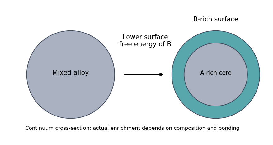
An illustrative surface-energy preference enriches the outermost layers without fixing a universal shell thickness
. Source. Details. Past exam of the MPhil in micro- and nanotechnology enterprise course of the University of Cambridge 2019 Paper 2 Section A(i) 13 ii Solution by Codex 0 2026-10-20
Codex 0 2026-10-20For the upper core-shell precursor, first reduce a precursor of metal A to make seeds; then introduce and reduce a precursor of B under conditions favouring heterogeneous deposition on those seeds rather than independent nucleation. Control added quantity, reduction rate and surface ligands to build a shell.
For the lower disordered-alloy precursor, reduce both metal precursors together so both metals enter the growing particles. Match their effective reduction rates by precursor chemistry, temperature, complexation or controlled feeding; otherwise sequential reduction can produce segregation instead of co-incorporation. Quenching or sufficiently mild growth can retain a disordered alloy before the later anneal. These routes need not initially produce equilibrium atomic arrangements.[ref]
Bimetallic Nanocrystals by Kyle D. Gilroy and others. Liquid-phase synthesis of core-shell and alloy architectures
Past exam of the MPhil in micro- and nanotechnology enterprise course of the University of Cambridge 2019 Paper 2 Section A(i) 13 i Solution by Codex 0 2026-10-20
Codex 0 2026-10-20A faceted, approximately equiaxed crystal is indicated. A truncated octahedron bounded by low-energy and facets is a plausible three-dimensional shape for an fcc metal particle; the hexagonal section alone does not uniquely distinguish it from other faceted polyhedra.
The Wulff construction minimizes at fixed particle volume. Place a plane with normal a distance from a common centre and take the inner envelope. Low-surface-energy orientations survive as large facets. Annealing permits diffusion toward this equilibrium morphology, provided the time is sufficient. For a supported or strained alloy, substrate adhesion and elastic energy modify this simple free-particle construction.
Past exam of the MPhil in micro- and nanotechnology enterprise course of the University of Cambridge 2019 Paper 1 Section B 9 i Solution by Codex 0 2026-10-20
Codex 0 2026-10-20From the illuminated side downward, the p-type gallium arsenide cap provides a low-resistance route to the front metal contact. It should remain beneath the contact grid but be removed from the optical aperture to reduce parasitic absorption. The wider-band gap p-type aluminium gallium arsenide window transmits much of the useful light and reduces front-surface recombination of carriers in the adjacent absorber. The optical-window and reduced-recombination rationale has a primary experimental basis in early heteroface devices.[ref]
High-efficiency Ga1-xAlxAs-GaAs solar cells by Jerry M. Woodall and H. J. Hovel. Applied Physics Letters 21 (1972), p. 379, transparency and surface-recombination rationale; p. 380, contacts and antireflection coating
The p-type gallium arsenide emitter and n-type gallium arsenide base form the p-n junction. Absorbed photons generate electrons and electron holes; diffusion and the junction's electric field direct them toward the appropriate contacts. The n-type aluminium gallium arsenide back-surface-field layer provides a barrier to minority holes moving toward the substrate and reduces rear recombination. The n-type gallium arsenide substrate supports the epitaxial layers and conducts majority carriers to the rear contact.
The front metal must collect current with limited shading and the back metal provides the return contact. Interpreting the patterned hatched region as the optical antireflection coating, it reduces reflected light over the exposed window. Carrier selectivity, low recombination, low series resistance and low shading must work together; the equilibrium junction field alone is not a source of electrical energy.
Past exam of the MPhil in micro- and nanotechnology enterprise course of the University of Cambridge 2019 Paper 1 Section B 8 iv Solution by Codex 0 2026-10-20
Codex 0 2026-10-20There is a verified inconsistency in the printed data: the original PDF says , whereas the relativistic de Broglie wavelength at is approximately :Use consistent length units, , and distinguish literal arithmetic from a physically consistent estimate. The familiar approximate Scherzer defocus is , or about with . Slightly different optimum-phase conventions use in place of , giving about ; both are underfocus by a few tens of nanometres. The manufacturer's tabulated values confirm that scale.[ref]
Scherzer focus by JEOL. glossary, underfocus convention and accelerating-voltage/spherical-aberration table
Using the question's additional numerical relation exactly as supplied, with , givesFor the physically appropriate rounded wavelength this is . The CTF itself gives an independent check: its first nonzero zero satisfies , so implies . The plotted condition is therefore a little less underfocused than the usual Scherzer setting and has a first-zero spacing near . The nominal and approximate optimization formula should not be treated as exactly reproducing every plotted parameter.
If the printed is retained literally, the approximate Scherzer formula instead gives , the supplied relation gives , and the plotted first zero requires . These do not describe a consistent microscope. The physically consistent comparison is approximately to optimum underfocus versus from the plot; the wavelength correction is explicit.
Past exam of the MPhil in micro- and nanotechnology enterprise course of the University of Cambridge 2019 Paper 1 Section B 8 iii Solution by Codex 0 2026-10-20
Codex 0 2026-10-20For a weak phase object, the contrast transfer function gives the signed transfer of an object's spatial Fourier components into intensity contrast. In a common convention,where is a cyclic spatial frequency, the defocus, the spherical aberration coefficient, and a coherence envelope. A zero suppresses that frequency; crossing a zero reverses contrast. The overall sign depends on the image convention, but the zeros do not. Single-image division by cannot recover information exactly at its zeros. The microscope manufacturer's discussion explicitly connects the first zero with interpretable resolution and the higher-frequency sign changes.[ref]
Phase-contrast transfer function, PCTF by JEOL. glossary, first-zero and envelope-function discussion
The plotted first nontrivial zero is at approximately . Hence the smallest spacing in the first uninterrupted contrast band is about . This axis is cycles per length, not an angular wave number requiring a factor of . Smaller spacings can contribute in later bands, but their contrast has reversed and requires appropriate interpretation or multiple-defocus reconstruction.
Past exam of the MPhil in micro- and nanotechnology enterprise course of the University of Cambridge 2019 Paper 1 Section B 8 ii Solution by Codex 0 2026-10-20
Codex 0 2026-10-20This is a conventional transmitted-beam bright-field transmission electron microscopy image containing high-resolution electron phase contrast and visible lattice fringes, rather than an element-specific chemical map. Relative to the scale bar, the smaller particle has an outer projected diameter of roughly . It is approximately rounded and contains a denser outer rim with several lighter internal regions separated by material. A porous or internally hollow particle is a plausible morphological interpretation; the image is not a simple featureless solid sphere.
Greater projected thickness generally removes more intensity from the transmitted beam, producing darker mass–thickness contrast. Different crystallite orientations also scatter intensity differently and give diffraction contrast. Local lattice fringes reveal crystalline material and changes of fringe orientation indicate more than one coherent domain. Bright/dark edge fringes also contain defocus-dependent Fresnel contrast; their width is not a direct shell-thickness measurement. Neither an exact alumina polymorph nor three-dimensional closed porosity can be uniquely established from this projection alone. Use calibrated fringe spacings and electron diffraction for phase identification, tilt-series imaging for void geometry, and a through-focus or dose series to test contrast artefacts.
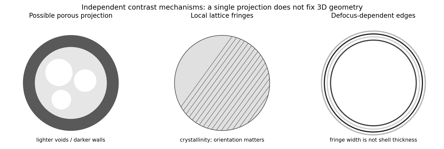
Original generic schematic separating projected porosity, crystallite orientation and edge-contrast interpretations
. Details. Past exam of the MPhil in micro- and nanotechnology enterprise course of the University of Cambridge 2019 Paper 1 Section B 8 i Solution by Codex 0 2026-10-20
Codex 0 2026-10-20Disperse a very small amount of the dry powder in a clean volatile solvent compatible with aluminium oxide, use brief gentle sonication to separate loose agglomerates, and place a dilute drop on a holey carbon-coated transmission electron microscopy grid. Wick away excess liquid and dry thoroughly. Look first at low magnification and select isolated particles or thin edges over holes, rather than an electron-opaque pile. Record a solvent-only grid to identify contamination and compare several independently prepared areas.
This is quick and preserves individual particles without mechanical thinning. However, spray pyrolysis can make hollow or porous particles that may fracture during sonication; sedimentation and drying can select sizes and aggregate particles. aluminium oxide is insulating, so charging or beam-induced changes can complicate images, and the carbon support can overlap weak contrast. Vary dose and dwell time to test stability. A projected image of one selected thin particle is not an unbiased three-dimensional size or porosity distribution of the whole powder.
Past exam of the MPhil in micro- and nanotechnology enterprise course of the University of Cambridge 2019 Paper 1 Section B 12 iv Solution by Codex 0 2026-10-20
Codex 0 2026-10-20A wireless sensor node combines a sensor, signal conditioning and conversion, a processor, a radio and a power subsystem. It can use a battery, a wired supply where practical, or local harvesting such as light, vibration or a thermal gradient, usually with a storage capacitor, supercapacitor or rechargeable battery to bridge interruptions. Harvested power must meet the time-averaged demand and storage must supply peak radio current.
Reduce power by duty cycling the sensor, processor and radio; use a low-leakage sleep mode and switch off unused peripherals. Buffer and batch data, transmit fewer unnecessary bits, use event-triggered acquisition when it meets the application, and reduce retries with a reliable link and an appropriate transmit-power level. Include wake-up, sensing, processing and communication energy in the budget: reducing payload alone may not reduce a radio dominated by startup overhead.
Pinned article: Introduction to the OurBigBook Project
Welcome to the OurBigBook Project! Our goal is to create the perfect publishing platform for STEM subjects, and get university-level students to write the best free STEM tutorials ever.
Everyone is welcome to create an account and play with the site: ourbigbook.com/go/register. We belive that students themselves can write amazing tutorials, but teachers are welcome too. You can write about anything you want, it doesn't have to be STEM or even educational. Silly test content is very welcome and you won't be penalized in any way. Just keep it legal!
Intro to OurBigBook
. Source. We have two killer features:
- topics: topics group articles by different users with the same title, e.g. here is the topic for the "Fundamental Theorem of Calculus" ourbigbook.com/go/topic/fundamental-theorem-of-calculusArticles of different users are sorted by upvote within each article page. This feature is a bit like:
- a Wikipedia where each user can have their own version of each article
- a Q&A website like Stack Overflow, where multiple people can give their views on a given topic, and the best ones are sorted by upvote. Except you don't need to wait for someone to ask first, and any topic goes, no matter how narrow or broad
This feature makes it possible for readers to find better explanations of any topic created by other writers. And it allows writers to create an explanation in a place that readers might actually find it.
Figure 1. Screenshot of the "Derivative" topic page. View it live at: ourbigbook.com/go/topic/derivativeVideo 2. OurBigBook Web topics demo. Source. - local editing: you can store all your personal knowledge base content locally in a plaintext markup format that can be edited locally and published either:This way you can be sure that even if OurBigBook.com were to go down one day (which we have no plans to do as it is quite cheap to host!), your content will still be perfectly readable as a static site.
- to OurBigBook.com to get awesome multi-user features like topics and likes
- as HTML files to a static website, which you can host yourself for free on many external providers like GitHub Pages, and remain in full control

Figure 2. You can publish local OurBigBook lightweight markup files to either OurBigBook.com or as a static website.
Figure 3. Visual Studio Code extension installation.
Figure 5. . You can also edit articles on the Web editor without installing anything locally. Video 3. Edit locally and publish demo. Source. This shows editing OurBigBook Markup and publishing it using the Visual Studio Code extension. 
- Infinitely deep tables of contents:




All our software is open source and hosted at: github.com/ourbigbook/ourbigbook
Further documentation can be found at: docs.ourbigbook.com
Feel free to reach our to us for any help or suggestions: docs.ourbigbook.com/#contact