An electrical calorimetry experiment asks whether a measured electrical work input accounts for a measured warming. The University of Iowa's demonstration uses an insulated flask containing water, an immersed heater, a thermometer, electrical meters and a timer. Its procedure compares the duration, electrical readings and temperature rise. The following low-power measurement design and synthetic readout develop that idea; they are not measurements reported by the demonstration. [ref]
5F15.10 - Electrical Equivalent of Heat by University of Iowa Department of Physics and Astronomy. Equipment and Procedure: insulated flask, immersed heater, thermometry, electrical meters and timed warming
Use a covered calorimeter with weighed water, an immersed resistor, a calibrated thermometer and gentle stirring. Put an ammeter in series with the heater branch and a high-input-electrical resistance voltmeter across the immersed resistor's terminals. Record , , temperature and room temperature before, during and after switching the heater on. Measure the electric potential difference at the heater, rather than at the supply: lead and contact electrical resistance outside the receiving boundary can consume power that never reaches the water. Account for voltmeter loading if the ammeter also includes the sensing branch's electric current.[ref]
The electrical readout gives operating electrical resistance when , and power . To test Ohm's law, obtain several pairs at the same temperature; one ratio alone cannot establish a linear response. For small electrical resistance, use four-terminal sensing to exclude lead drops and reverse electric current to test stable offsets from the thermoelectric effect. Use brief low-power resistance measurements if the intended result is the unheated value: the test itself causes Joule heating.
For a covered assembly at approximately constant pressure, with negligible evaporation, negligible endpoint mechanical energy changes and no phase transition, takeHere is the water's specific heat capacity at constant pressure, is the participating vessel, heater and sensor heat capacity, is signed outward heat leakage, and is stirring work entering the assembly. The storage term approximates its enthalpy change; for a rigid fixed-volume receiver use the corresponding heat capacity at constant volume. Calibrate independently if the purpose is to test electrical input against thermal storage. Using the same heating run to define and then claiming it verifies the equality would be circular.
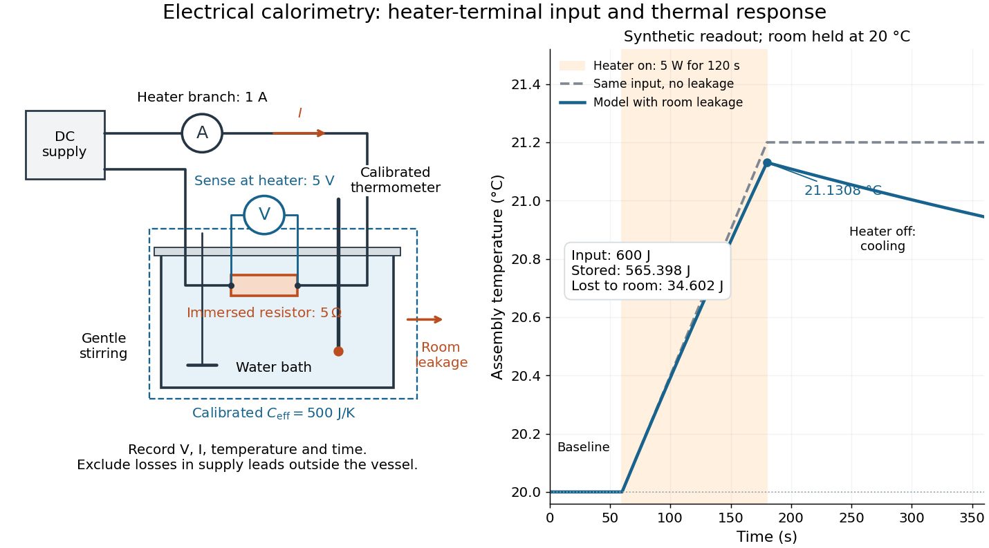

For the synthetic trace, stipulate , , , , room temperature , and loss coefficient , with negligible stirring input. The heater runs for , beginning at room temperature. The calorimeter heat-loss correction model isIt predicts , , storage and outward loss . Neglecting leakage undercounts deposited energy by about ; assuming no loss predicts . After switching off, the excess temperature undergoes exponential decay with time constant . A cooling slope can estimate only with known and a credible single-temperature model.
Controls separate causes of a temperature rise. Check the electrical meters' zeros and thermometer calibration; keep water mass, immersion, lid and stirring fixed between runs. Record a heater-off stirred baseline to estimate sensor drift and stirring input. Repeat cooling runs over the same temperature range to estimate environmental heat transfer; a baseline taken only at room temperature cannot measure warming-dependent leakage. Vary electric current while keeping and initial thermal conditions comparable: corrected deposited energy should scale as for equal durations. An independent calorimeter calibration or known reference heat capacity makes this a quantitative test rather than a qualitative observation.
Finite sensor response, incomplete thermal equilibrium, changing or heat capacity, evaporation, and imperfect loss corrections limit the inference. A final temperature alone cannot distinguish smaller electrical input from larger heat leakage or a larger participating heat capacity. Agreement tests the stated assembly and its energy accounting; it does not show that all electrical work in arbitrary devices becomes heat.
Historically, the Royal Society's archive description of James Prescott Joule's manuscript dated 13 October 1840 records a coil of wire in a jar of water, a thermometer and a galvanometer, and summarizes his inference that warming depends on electrical resistance and the square of electric current intensity. This electrical experiment precedes Joule's paddle-wheel experiment; the input here is electrical work, whereas the paddle supplies mechanical work. The catalogue, rather than the inaccessible manuscript images, supports this account. [ref]
Archive catalogue record AP-23-34: On the production of heat by voltaic electricity by The Royal Society Archives. Royal Society Archives, AP/23/34, Description and Date: apparatus, resistance dependence and duplicate-ratio conclusion; manuscript dated 13 October 1840
Articles by others on the same topic
There are currently no matching articles.