Across a radial section, the narrow-gap indium gallium nitride layer lies between wider-gap n-GaN and p-GaN. A suitable type-I band alignment has a downward conduction-band offset and upward valence-band offset in the indium gallium nitride, confining electrons and holes to the active layer. The original band sketch isolates those offsets; the complete junction also has doping-induced band bending.
At thermal equilibrium the Fermi level is common throughout. Forward bias separates the electron and hole quasi-Fermi levels, injects carriers from the n- and p-regions and permits electron-hole recombination in the thin active layer. A full radial line through the wire crosses two copies of the shell well; a core-to-exterior radial coordinate crosses one.
The 5 nm indium gallium nitride shell is the quantum well active region, not a metallic contact. Finite band offsets, confinement and polarization fields affect its transition energy; the bulk gap alone is insufficient.
A plausible role for the SiN mask is selective-area growth: restrict nucleation to exposed windows and suppress parasitic deposition between wires. Retained insulating material can also help prevent unwanted electrical paths during later processing. Which role dominates depends on the actual fabrication sequence. The cited source concerns core-shell single-wire LEDs and contact engineering, so a qualitative band sketch does not reproduce its complete device model.[ref]
InGaN/GaN Core-Shell Single Nanowire Light Emitting Diodes with Graphene-Based P-Contact by Maria Tchernycheva and others. 2014, pp.2456–2465, device/material system and contact architecture
Two suitable epitaxial techniques are metalorganic vapour-phase epitaxy and molecular beam epitaxy.
MOVPE supplies metalorganic group-III precursors and a reactive nitrogen source in a flowing gas. Surface reactions, mass transport and selective nucleation control growth; it is well suited to conformal radial growth and relatively high throughput. molecular beam epitaxy supplies molecular/atomic beams in high vacuum, with beam fluxes and shutters controlling delivery. It offers precise flux switching and in-situ surface monitoring, but flux, geometry and nitrogen activation can limit growth rate and conformality. Neither method automatically gives identical growth on all wire crystal facets.
For an overall target near , MOVPE is a natural choice. This is a practical selection, not a theorem that molecular beam epitaxy cannot attain that rate.
Prepare the substrate/buffer and patterned SiN growth mask; grow donor-doped gallium nitride cores with controlled axial morphology; change conditions to favor radial deposition and incorporate indium for the thin indium gallium nitride active shell; then overgrow acceptor-doped p-GaN without degrading the active layer. Finally expose/contact the core and shell appropriately. Monitor facet-dependent thickness and indium content, and characterize the interfaces. If the active-layer normal rate itself were , 5 nm would take 7.5 s; the stated overall rate does not establish that the alloy shell actually grows at that same rate.
One possible cause is a different indium gallium nitride thickness or indium content that shifts this wire's emission away from 420 nm. The detected intensity at one wavelength then falls even if its integrated radiative efficiency is unchanged. Since , composition, strain, confinement and internal fields can all move the transition relative to that detection energy.
A second physically different possibility is poor active-layer quality: roughness, composition segregation or strain relaxation can introduce defects and nonradiative recombination. Locally thinner or discontinuous shell regions may also permit carrier leakage.
Measure the full spectrum and integrated emission, rather than one spectral channel. Time-resolved luminescence, excitation-dependent measurements and local structural/compositional characterization can distinguish a spectral shift, changed carrier injection and an increased nonradiative rate. The single-wavelength observation alone does not uniquely identify lower internal quantum efficiency or one growth defect.
A common implementation uses a gallium arsenide/aluminium gallium arsenide heterostructure with a two-dimensional electron gas near the interface. electrons supplied by remote donors occupy quantized normal-direction states, while an undoped spacer reduces ionized-impurity scattering. Surface metallic gates, insulated from the conducting layer, deplete selected regions when negatively biased.
Leave a small conducting island bounded by depleted regions and connect it weakly to source and drain reservoirs through two tunable constrictions. A plunger gate controls the island potential/population; barrier gates control tunnel coupling. Ohmic contacts connect the reservoirs to the measurement circuit. Vertical heterostructure confinement plus lateral depletion force defines the dot. A 2DEG without lateral gates would remain extended in its plane.
The original device diagram labels the gates, island, tunnel barriers and reservoirs. Charge stability and spectroscopy versus gate/bias should verify that an isolated weakly coupled island has actually formed; a lithographic outline alone is insufficient.
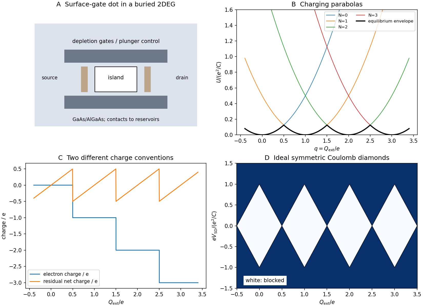
Gate-defined dot, charging parabolas, charge steps and Coulomb diamonds
. Original schematic and constant-capacitance model plots. The conductance map is an idealized symmetric-bias cartoon, not experimental data or a microscopic tunnelling calculation. Details.
Let be the island's total electrostatic capacitance and the charge offset induced by gates, reservoir potentials and fixed background charges. In the constant-capacitance model,Taking the difference givesChanging gate voltage changes approximately linearly, for example through .
For fixed , is a parabola. At small temperature/bias, the preferred integer is the one nearest ; the equilibrium energy follows the lower envelope of these parabolas. Adjacent charge states become degenerate at , allowing small-bias sequential current when the two barriers are transmissive.
The excess-electron charge is a staircase. If “net charge” includes the induced compensating charge, define ; that residual charge is a sawtooth between and in equilibrium. The opposite sign convention reverses the sawtooth. State the charge convention: an integer electron-charge staircase and a residual electrostatic-charge sawtooth describe different quantities.
A larger source–drain bias opens an energy window between reservoir electrochemical potentials. When a charge-addition/removal transition enters that window, sequential tunnelling becomes allowed even away from a zero-bias degeneracy. The low-conductance regions in a gate/bias map are Coulomb diamonds.
For an illustrative symmetric device with reservoir potentials , let and . In the charge- interval, the classical blockade domain isIt shrinks to zero at . Unequal capacitances change edge slopes and voltage division; the figure's symmetry is a chosen model, not a universal device property.
Quantum confinement adds discrete single-particle levels and spin structure. In a constant-interaction approximation, successive addition energies contain plus the relevant orbital spacing, so diamond sizes need not all match. Excited-state tunnelling can produce extra conductance lines. At stronger coupling, cotunnelling and charge fluctuations can give leakage beyond a simple sequential classical model. Thus temperature and coupling must be small enough to resolve the charging and level structure separately.
An initially localized escaping electron occupies a superposition of lead momentum states. In a uniform free one-dimensional lead,A packet centered at moves with group velocity and generally spreads because its components have different velocities. For an initially unchirped minimum-uncertainty Gaussian wave packet,This illustrates dispersive evolution; the actual emission contact determines and whether only outward-propagating components are appreciable. It does not instantaneously become a single lead plane wave.
A single-electron transistor used as a sensitive electrometer exploits Coulomb blockade: a nearby charge shifts the offset and therefore the conductance peaks. This requires stable calibrated capacitances and low charge noise, rather than merely a small conductor.
A useful five-part classification is electrostatic double-layer, dispersion, steric, depletion force and solvent-mediated interactions. It is a practical classification rather than a unique exhaustive list.
Electrostatic double-layer forces arise from surface charge and mobile-ion redistribution. Like-charged surfaces often repel; opposite charges can attract. Their range changes with salt screening. London dispersion forces comes from correlated electronic fluctuations and is one contribution to Van der Waals force; its sign and strength across a medium depend on dielectric response.
steric stabilization occurs when adsorbed or grafted layers overlap, increasing chain confinement and/or local osmotic free energy. depletion force arises when smaller nonadsorbing solutes are excluded from a narrow gap: their greater accessible volume outside favors bringing the large particles together. Structured-solvent forces include short-range hydration force and hydrophobic attraction; their microscopic origin differs from the depletion force of an added solute.
The original sketches show double-layer overlap, a polymer-coated gap, depletion force exclusion and solvent structure, alongside a dispersion-potential curve. A realistic suspension can experience several simultaneously. Charge neutrality of a particle does not remove dispersion, steric or solvent-mediated interactions.
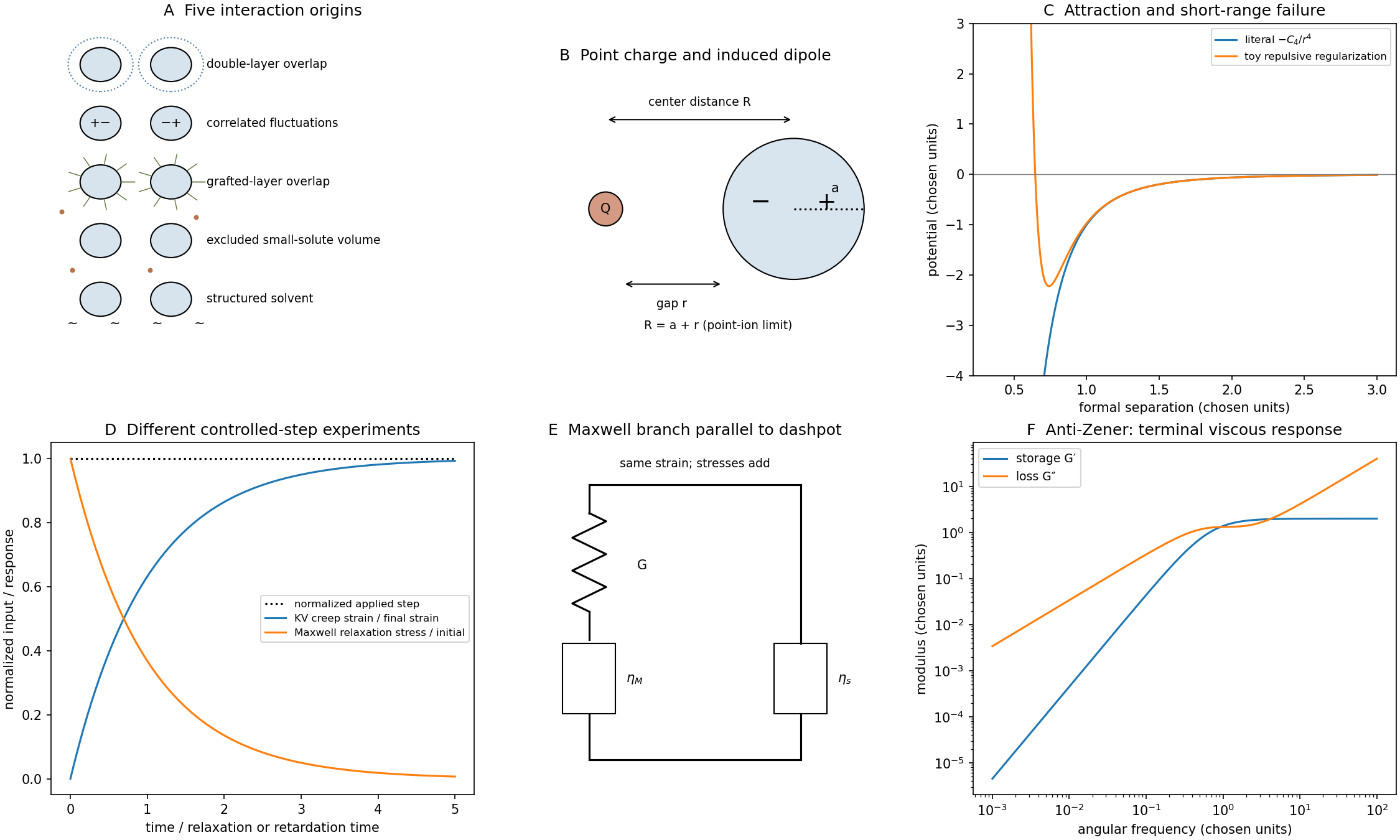
Colloidal interaction mechanisms and viscoelastic material response
. Original interaction cartoons, model potentials, step-response curves and parallel Maxwell–dashpot rheology. Potential parameters and rheological constants are chosen illustrative values, not fitted measurements. Details.
Write . Differentiating the stipulated potential givesFor positive , the force points toward smaller separation for either sign of .
Its physical origin is charge-induced dipole attraction, rather than London dispersion forces. A point-charge field induces and the energy cost of inducing that moment gives . The charge changes the electric dipole moment; it does not, within this linear model, change the intrinsic coefficient . For a conducting sphere in a uniform medium, ; other dielectric contrasts give another electric polarizability.
There is a distance inconsistency in the stated model: the point-charge field uses center-to-center separation , whereas the question calls a surface gap. For a point ion and sphere, . A controlled far-field dipole model therefore uses , with . The boxed derivative is the literal result for the given mathematical ; it is not a justification for extending that dipole formula to contact.
For , the given model predicts attraction proportional to in force, independent of the ion's charge sign; the energy is proportional to and vanishes at large separation. A larger electric polarizability gives a stronger interaction.
This is induction by a charged object. Ordinary nonretarded London interaction between two small neutral polarizable objects instead has an energy dependence; geometry-integrated colloidal dispersion laws can have other powers. Calling the specified law a generic dispersion force would conceal its charge-dependent origin.
Attraction can favor association or adsorption. A stable suspension normally requires an opposing free-energy barrier, such as double-layer or steric repulsion, relative to Brownian motion. Salt, surface coatings and solvent quality alter that balance. However, one ion–particle pair potential alone does not establish the phase behavior or aggregation rate of a many-particle suspension; concentrations, diffusion, surface chemistry and the remaining interactions also matter.
The literal curve is monotone increasing from at toward zero from below as :Taken literally at a zero gap, it predicts an unbounded collapse energy and force. That extrapolation is outside the far-field dipole approximation and cannot describe actual touching matter.
Finite atomic/ionic dimensions, electronic overlap and Pauli repulsion supply short-distance constraints. Solvent and hydration layers, steric coatings and surface chemistry can add further contributions. An illustrative regularized model is with ; it has a finite minimum at and becomes repulsive at shorter distances. This is a schematic regularization, not a derived complete ion–sphere contact law.
Separately, correcting the center-distance convention to already removes this particular divergence from the far-field expression, but does not make a dipole approximation accurate at contact. Near-field multipoles and microscopic repulsion still require a better model. Calibrated colloidal probe technique measurements can test where a long-range force model ceases to agree with actual approach curves.[ref]
direct measurement of colloidal forces using an atomic force microscope by William A. Ducker and others. 1991, pp.239–241, sphere–plane force measurements and short-range deviations
In a material creep experiment, apply a small step shear stress and measure the resulting strain. The creep compliance is . An elastic solid reaches a bounded strain; a fluid can continue deforming.
In a stress-relaxation experiment, impose a small strain step and measure stress while holding the deformation. The relaxation modulus is after the loading transient. A fluid's stored shear stress can decay to zero, while an elastic solid retains a nonzero long-time contribution.
The original curves distinguish the controlled input from measured output. The strain/stress must be small enough for linear response, and real finite loading rise time, instrument compliance, wall slip and temperature must be characterized. Otherwise an instrumental transient can be mistaken for a material relaxation mode.
A strain increment applied at time contributesLinearity lets the contributions add, and time-translation invariance makes the kernel depend only on elapsed time:In the continuous limit this is Boltzmann superposition,The material's prehistory must be included, or it must start from a specified relaxed state. Aging, yielding and large-strain changes can violate this simple superposition. An instantaneous Newtonian contribution can be written separately as ; for an ideal step it is an impulse, not an ordinary finite relaxation tail.
A Kelvin-Voigt model element places a spring and dashpot in parallel, givingUnder a stress step from a relaxed state,It captures delayed but bounded material creep and eventual strain recovery after unloading, rather than steady terminal flow.
For an ideal strain step,After the loading impulse, the stress remains . The model does not produce a gradual stress-relaxation tail at held strain. A real finite-rate ramp replaces the impulse by a finite dashpot stress during loading, but the subsequent held-strain stress is still constant. Thus this model describes material creep retardation but not a solid's genuine time-dependent relaxation toward another finite modulus.
Let the Maxwell branch contain spring modulus and series viscosity , in parallel with a dashpot of viscosity . The branch strains are equal and stresses add. Writing for the Maxwell stress,For and ,Multiplying the Maxwell fraction by givesThe sign of the imaginary coefficient depends on the phasor convention; these expressions use , so represents dissipation. In the time domain, the equivalent constitutive relation isThe original mechanical schematic shows the series spring/dashpot branch separately from the parallel dashpot.
For ,andThus the material flows at sufficiently low frequency: its static shear modulus vanishes and its terminal response is viscous. The dashpot in the Maxwell branch allows its spring stress to relax, so there is no permanent elastic path through the parallel network.
Articles by others on the same topic
There are currently no matching articles.