Use the convention for the harmonic force and displacement complex amplitudes. Substitution in the forced harmonic oscillator equation givesIts magnitude and phase relative to the force areAt zero frequency, and . At , ; at high frequency the phase approaches . For light viscous damping, the quality factor is large and there is a tall narrow displacement peak close to .
To find the displacement peak, minimize the squared denominator:The nonzero minimum givesFor stronger damping there is no positive-frequency displacement maximum. When and ,The inertia then dominates the restoring and damping forces.
The four supporting springs act in parallel, so their total spring constant is . The driving angular frequency is . The force-driven vibration isolation estimate givesAt this mass, , and , so the assumptions are consistent. The exact forced amplitude isIt is indeed close to , but it is slightly above the strict requested bound. Setting the exact expression to gives the high-mass thresholdChoose a mass strictly greater than this threshold for a strict inequality; is a suitable rounded choice. Simply rounding the high-frequency estimate down would not guarantee the bound.
Measure downward displacement relative to the former mean equilibrium. The added changes the equilibrium byAssume the load is deposited without a significant impact impulse and then moves with the table. The moving mass becomes . Ignoring the tiny pre-existing vibration in the sketch, the added-load step response of a supported table isFor the estimated mass, , the envelope time is , and the period is about . The table overshoots and rings about the new equilibrium, with the displacement starting continuously at zero and with zero initial slope. A real impact adds an initial-velocity transient; the problem gives no impact history. The residual driven vibration, of order a micrometre, can be superposed.
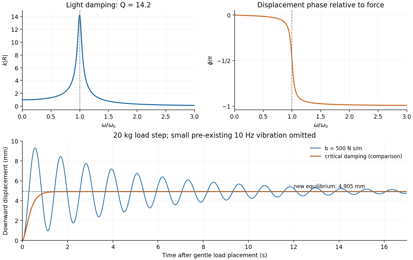
Lightly damped response amplitude and phase, followed by the table's load-step displacement and a critically damped comparison
. Details. 
To settle quickly after loading, critical damping is preferable to the supplied weak damper:Using the strict-bound mass instead changes this by less than . This eliminates free ringing while avoiding the slow tail of severe overdamping. In the stipulated external-force model, greater damping also reduces the steady forced amplitude; there is no finite optimum based solely on that amplitude. A critical or near-critical value is a practical compromise for rapid settling. If the disturbance were specified as floor displacement transmitted through the legs, damping would introduce an additional transmission tradeoff, but that is a different forcing model.
Superpose two nearby harmonic waves. The identityseparates a rapid carrier from a slow beat envelope. A constant point of the envelope moves at , which tends toas the components approach one another. Equivalently, expand a narrow wave packet spectrum around : . Factoring the carrier out of its Fourier transform representation leaves an envelope depending on . This interpretation requires a narrow spectrum and little attenuation or distortion; higher derivatives of the dispersion relation can change the envelope shape. The carrier phase velocity is and need not equal .
For the wavelength in the medium, , differentiate :The distinction in group velocity in material and vacuum wavelength coordinates is essential for the numerical data. For incident vacuum wavelength , differentiation of instead givesThus the printed derivative identity is valid, but its wavelength coordinate cannot be carried unchanged into data specified before refraction.
The wavelengths specified for incidence from vacuum are . With fixed incident angle , Snell's law gives and . At the central wavelength,Use a central difference, converting the angle change to radians:The group index from refracted-angle dispersion isDirectly inserting the incident vacuum wavelengths into would instead give . That is a plausible intended rough answer, but it mixes wavelength coordinates; the boxed result consistently uses the incident data. The two agree only to first order in a sufficiently small dimensionless dispersion correction.
Taking as the distance travelled in the medium, the narrowband group delay isIf denotes a slab thickness measured normal to the interface instead, the central ray travels , giving about . The coordinate-mixed velocity above would give for a path; it should not replace the consistent calculation silently.
The pulse envelope travels at the local group velocity, while individual carrier crests move at the phase velocity. In general, variation of group velocity across the pulse spectrum produces different delays, temporal broadening and chirp. Absorption can reshape the spectrum and envelope as well. The refraction data also show wavelength-dependent angles, so a finite-width incident beam acquires spatial separation of its spectral components. The supplied first derivative determines the central delay but does not specify a pulse duration, absorption spectrum or reliable second derivative of the dispersion relation; it therefore does not determine a numerical broadening, or its sign. If propagation phase is effectively linear across a sufficiently narrow spectrum, the leading approximation is a delayed pulse with unchanged shape.
Use Fourier transform convention . The convolution theorem givesA finite array of very narrow slits at , , has transmission proportional to . It can be constructed by multiplying an infinite Dirac comb by a finite window. The infinite comb transforms to a reciprocal comb; the finite window convolves each reciprocal peak with a narrow sinc-shaped amplitude. Thus increasing the illuminated length narrows each Fraunhofer diffraction peak.
The exact finite sum makes the argument quantitative:Its normalized intensity is . Principal maxima occur at ; their first zeros are displaced by . Replacing the ideal narrow slit by a finite slit function convolves the array in real space, multiplying this field by the single-slit Fourier transform. Field amplitudes are transformed and combined before their squared modulus is taken.
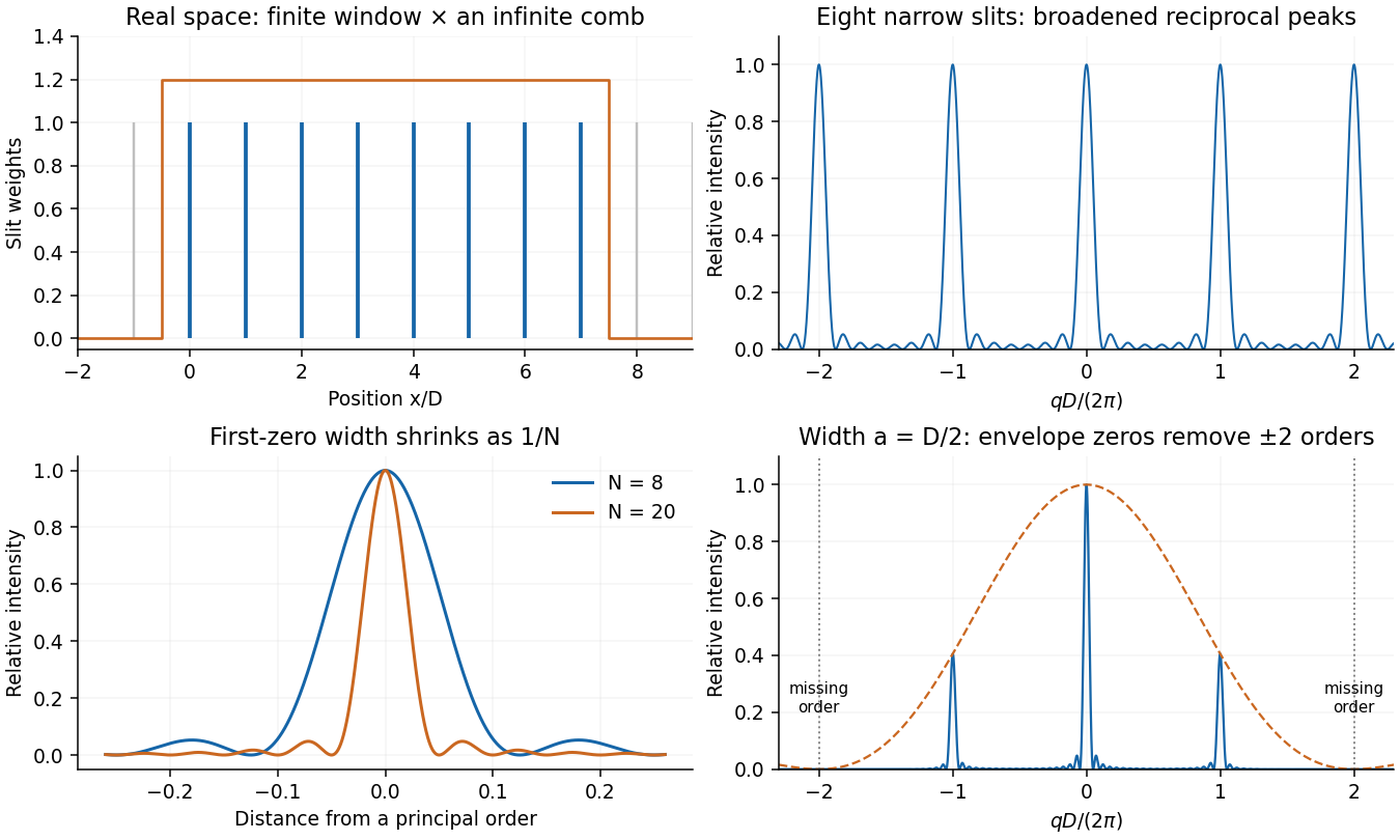
A finite narrow-slit array and its Fourier intensity, showing how the principal peaks narrow with slit count
. Details. 
The pitch corresponding to is . The normal-incidence diffraction grating equation givesThis locates the array-factor maximum; the single-slit envelope must also be nonzero for an observable peak.
Near order , the first angular zero from a principal maximum is . Two wavelengths have peak separation . Equating them applies the Rayleigh criterion and gives the resolving power of a diffraction grating,Here the required resolving power is , so in second order . The illuminated width is thereforeWhether one counts the full illuminated window or the first-to-last slit-centre distance changes the width by one pitch and is immaterial at this precision. The result assumes negligible aberrations and adequate slit illumination and coherence.
The angular dispersion at the chosen order isFor a collecting lens with its axis directed along the selected second-order beam, the local focal-plane separation isA basic one-pixel separation criterion is therefore . A more reliable two-pixels-per-resolution-interval choice is . Finite pixels integrate the pattern, so sampling and pixel response should not degrade the grating's optical resolution.
This pixel sampling of a grating spectrum depends on the layout and criterion, neither of which is fully specified. If the detector is instead described by relative to the incident-axis coordinate, the derivative contains an additional and gives separation, or about for two-pixel sampling. The more approximate paraxial mapping gives . These are stated alternatives rather than one falsely precise universal pixel width.
For a slit of width , the single-slit diffraction amplitude is proportional to . At a grating maximum, , so the envelope factor isThe specified gives at . ThusThe grating maximum coincides exactly with the first single-slit minimum for each wavelength. The preceding width and detector calculations describe the ideal array factor, but this particular rectangular-aperture grating cannot deliver the assumed second-order signal. Pixel refinement cannot repair the missing optical peak. One must change the aperture duty cycle or grating profile, or use an available order and recalculate its resolving power.
Let the first ray reflect at the upper surface and the second traverse the film, reflect below, and emerge at a laterally displaced point. Its internal round-trip geometric length is , but the external path to a common outgoing wavefront must also be included. The lateral separation is , whose projection along the external ray is . The net optical path difference is thereforeusing Snell's law . Multiplying by the vacuum wavenumber givesFor the usual index ordering , including the stated later value , both reflections are towards higher refractive index and both reverse the electric-field sign. Their relative reflection phase is therefore zero; is also their total relative phase modulo . A different index ordering or polarization-dependent reflection phase would require that additional term.
At the same output in air, use incident intensity . The two specified output amplitudes, including their common reflection sign, give the thin-film interference resultThe output is a cosine with mean , period , and extremaThe unequal amplitudes prevent a dark minimum; their interference visibility is . This is the stipulated two-beam model: the supplied amplitudes already include propagation and transmission factors, and internal re-reflections are excluded by the stated assumption. They need not be recomputed from the later index value.
Eliminate the internal angle using Snell's law:Neighbouring bright fringes differ in phase by . The local angular fringe spacing of a transparent film therefore givesWith , , and ,The data specify a local spacing near , so differentiating is appropriate; choosing particular neighbouring fringe angles slightly shifts this approximate result. The phase decreases as incidence angle increases.
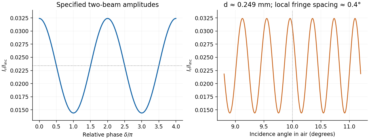
Two-beam reflected intensity versus phase and angular fringes for the inferred film thickness
. Details. 
At normal incidence, the propagation phase is . Different film thicknesses therefore produce bright and dark contours of equal thickness, with adjacent same-type fringes differing by . Under monochromatic illumination these are intensity variations of the incident colour, rather than a rainbow.
For the usual case , reflection at air-oil reverses phase while reflection at oil-water does not. The additional relative makes reflected minima occur at and maxima at . If the oil index were below the water index, the phase-reversal pattern would change and these conditions would interchange. The thinnest regions need not be completely dark because the two reflected amplitudes need not match; at vanishing thickness the residual reflection approaches that of the air-water boundary. Surface motion changes the thickness contours and moves the fringes.
Articles by others on the same topic
There are currently no matching articles.