The Peltier effect is heat transfer associated with an electric current crossing a junction between materials with different Peltier coefficients. At fixed junction temperature, its contribution changes sign when the conventional current reverses. A junction can absorb heat from its surroundings for one direction and release it for the other. Joule heating, proportional to the square of the electric current, accompanies this transport but does not reverse sign. Consequently, observing a warm device alone does not identify the Peltier effect.
This makes the Peltier effect useful as an electrically controlled heat pump: reversing the supply can switch an object's thermal role without changing any plumbing. In thermoelectric cooling, however, the useful cooling is the junction's absorbed heat minus returning heat conduction and its share of Joule heating. Increasing electric current eventually makes cooling worse. The distinction between transported heat and net cooling is the central practical lesson of the thermoelectric cooler energy balance.
At uniform temperature, define the material Peltier coefficient by transported heat current along positive conventional current:Its units are . In one dimension, , with electric current density and thermal conductivity . Here heat excludes the electrochemical potential contribution to total energy flux.[ref]
Now orient positive conventional current from material A into material B, at a common junction temperature . Define as heat taken from the junction's thermal surroundings. The outgoing transported heat minus the incoming transported heat givesThe local released heat is . Authors defining a junction coefficient by released heat therefore use the opposite sign. Exchanging A and B reverses the coefficient; reversing at fixed A and B reverses the junction's thermal response. An individual material coefficient and a junction difference are different quantities.
For an original stipulated example, choose and at . The Kelvin thermoelectric relation gives , . A positive flowing A to B absorbs . A separate junction electrical resistance would dissipate for either direction. If all that dissipation heats the junction, its net absorbed power is forwards and backwards. These numbers illustrate a chosen thermal accounting boundary, not measured material data or a universal allocation of contact heating.
With the Seebeck coefficient convention at zero electric current, and the transported-heat convention of Peltier coefficient, the Kelvin thermoelectric relation is is absolute temperature in kelvins; use consistent material references. This scalar linear response relation assumes local thermal equilibrium and reciprocal transport without time-reversal-breaking fields or order. Onsager reciprocal relations supply the symmetry; conservation of energy alone is insufficient. A magnetic field requires a reversed-field reciprocity comparison.[ref]
In particular, the A-minus-B thermocouple coefficient in Seebeck effect is , whereas absorbed junction heat for conventional current A to B uses . There is no contradiction: terminal voltage order and crossing direction are separate choices. Multiplying a measured voltage by an absolute temperature without specifying these choices does not determine junction heating.
A short reciprocity calculation makes the factor visible. At a common reference temperature, write the local linear response with electrical driving field and heat flux asAt , the Seebeck coefficient convention gives . At , the Peltier coefficient is . Thus gives . The chosen forces are conjugate to the fluxes in the local entropy production, ; arbitrary rescaling of just one force would spoil this argument.
The relation is local. Varying permits distributed Thomson effect heating, with ; the constant-coefficient model below omits it. Endpoint substitutions into a constant-property formula can therefore break its energy accounting.
An actual institutional protocol is CTU's Measurement of characteristics of a Peltier cell. Its cooling run uses a water container, an insulating cap and a current-limited supply; both face temperatures are recorded every minute while electric current is monitored. The apparatus includes a water-cooled exchanger, copper blocks and brass containers. The heating run resets the water near room temperature before reversing polarity. The handout specifies no thermometer type and reports no dataset. Its modular junction geometry is shown separately from the external thermal assembly.[ref]
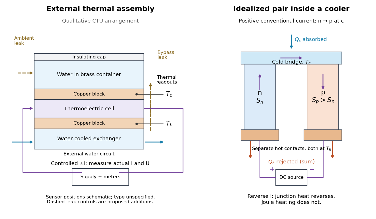

The following is a proposed quantitative extension. Keep the physical face labels fixed throughout reversal: c denotes the observed object's side and h the exchanger side, even if their actual temperatures change order. Use an independently read thermometer at each thermal contact and log the actual signed electric current and terminal electric potential difference. Maintain reproducible contact pressure and contact layers. A sensor in water measures water temperature, which need not equal the face temperature during a transient; verify mixing and contact equilibration before using it as a face reading. Do not interchange sensor leads when reversing the supply.
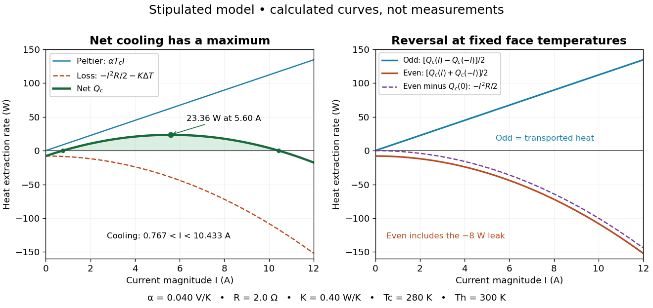
The strongest separation compares runs at the same , water mass, contact conditions and environment, rather than subtracting arbitrary final temperatures. One option is short initial-rate runs after resetting the whole assembly to a reproducible state. Define as the net power entering the monitored object, inferred from its calibrated effective heat capacity and initial temperature slope. In a simple symmetric model, let include background heat transfer at that state and the dissipated power reaching the object. Thenwhere in the thermoelectric cooling model below. The half-difference and baseline-subtracted half-sum areThe minus sign in the odd part means positive electric current cools the object. The even part has to subtract the zero-current baseline: otherwise heat conduction and ambient exchange remain mixed with Joule heating. Independently measured heat capacity is essential for converting a thermal slope into watts; include the blocks, container and water that actually equilibrate on the measurement timescale.
Useful controls are zero-current drift at several matched temperature differences, equal-magnitude positive and negative electric currents, and repetition of a sequence such as with thermal resets. A calibrated small heater on the object can test the heat capacity and lost-heat correction independently. Check Joule heating in supply leads and contacts, bypass heat conduction through supports and wiring, and ambient convection and thermal radiation. Insulation reduces a leak; it does not establish that it is zero. Measure terminal power at the module boundary so lead losses are not mistaken for module heating.
An odd thermal response supports a reversible current-coupled contribution, but does not by itself locate all of it at one junction: the Thomson effect in nonuniform leads can also be odd. Sensor offsets, unequal current magnitudes, drifting thermal contacts and different junction temperatures during the two runs can contaminate both parts. In particular, heating proportional to is even only when the compared electrical resistance is the same. CTU's qualitative reversal illustrates switching heating and cooling; the matched-state controls above would be needed for a coefficient measurement.
Thermoelectric cooling uses the Peltier effect to remove heat from a load using electrical work. A typical thermoelectric module connects many pairs of different semiconductors electrically in a series circuit and thermally in parallel between two faces. For an idealized pair with , positive conventional current crosses n to p at the cold bridge and p to n at the hot return. With common bridge material and isothermal contacts, the intervening metal contributions telescope: the net pair coefficient is . For identical pairs define the module Seebeck coefficient .
Choose fixed face temperatures , , module electrical resistance and open-circuit thermal conductance . All three module parameters are constants over the chosen operating range. Positive is the orientation absorbing Peltier effect heat at c. Define as net heat extracted from the cold reservoir per unit time, as net heat delivered to the hot reservoir per unit time, and as electrical power entering the module. Despite the conventional letters , both denote power in watts, not accumulated energy. Ferrotec gives the corresponding single-stage equations and distinguishes module performance from bypass leaks.[ref]
The chosen steady-state model isHere is the terminal voltage drop along positive electric current through the module. Its Seebeck effect term opposes the cooling supply. The cold Peltier effect term removes heat; Joule heating and returning heat conduction reduce the available cooling. At zero electric current, : the passive leak warms c and removes heat from h, consistent with the stated signs. Subtracting the two face equations cancels heat conduction and gives the electrical power, an independent conservation of energy check.
The factor one half is an ideal-model result, not a universal rule for every contact. To see its origin, let run from cold to hot along a uniform equivalent leg of length , cross-sectional area , electrical resistivity and thermal conductivity . With constant coefficients, insulated sides and no Thomson effect, steady conservation of energy givesThe Fourier's law heat current in the positive direction is . At it equals , and at it equals , using and . Adding the local transported heat current gives the two face equations. Summing equivalent legs preserves this accounting. Nonuniform material properties, side losses or asymmetric contact dissipation require a revised model.
For an original toy module, stipulate , , , and . At ,The coefficient of performance is defined here only for refrigeration with and . The hot-side assembly must remove , not just the extracted . These are stipulated calculations, not measurements or a commercial module specification.
At the same fixed face temperatures but , the same boundary definitions give , , and . The formerly cold face is now heated; the formerly hot reservoir supplies . Still . Reversal changes the linear terms, while and the leak at fixed temperatures remain unchanged. Holding the old labels fixed makes this check meaningful.
The corresponding steady entropy production of the module is the outgoing reservoir entropy minus the incoming reservoir entropy:The Peltier effect terms cancel because they carry the same entropy at each end. This cancellation explains the reversible coupling; it does not make finite-resistance operation reversible. In the toy example the two positive contributions are approximately and , giving for either current direction. In cooling operation, combining this inequality with the energy balance gives the Carnot refrigerator limit , equal to for these reservoir temperatures. A coefficient of performance above one would describe transported heat per electrical work, not the creation of energy.
At fixed face temperatures, differentiation of the thermoelectric cooler energy balance givesThus current chosen for maximum cooling power is not automatically current for maximum coefficient of performance. Cooling exists only when , and then only between the two positive rootsAt equality the parabola merely touches . For the toy module the interval is approximately , with and . At , the object is heated even in the nominal cooling polarity: . This mathematical interval supplies no permission to exceed an actual device's current or temperature ratings.

The fixed-face constraint matters. With fixed but a freely cooling object, must be solved from its heat load and leaks rather than held at while claiming an arbitrary temperature drop. For zero load and optimal current, the same model givesHere has units and is a module parameter. The toy model gives and when . This is an ideal zero-load limit with stipulated constant properties; cooling a real load requires above zero and reduces the attainable drop. Contact thermal resistance, a warming heat sink, external leaks and temperature-dependent coefficients further change the result. Electrical control is convenient, but conservation of energy still requires a thermal path that removes the extracted heat plus the electrical input.
Articles by others on the same topic
There are currently no matching articles.