As of my last knowledge update in October 2021, Trackbuster does not refer to a widely recognized brand, product, or service. It's possible that it's a new or niche product, service, or company that emerged after that date, or it may refer to a software or tool meant for a specific industry or use case, potentially in areas like logistics, event management, or social media tracking.
Uuencoding (Unix-to-Unix encoding) is a binary-to-text encoding scheme that was commonly used to encode binary files for transmission over protocols that only support text data. Originally developed for Unix systems, uuencoding is designed to convert binary data into a text format that can be sent via email or other text-based systems without loss of data integrity.
X-Face is an experimental email header field that is used in conjunction with the X-Face MIME type to represent a small image or icon associated with the sender's email address. The image is typically sent as a base64 encoded string in the email header, allowing email clients that support the X-Face feature to display the image next to the email.
An FTP bounce attack is a type of network attack that takes advantage of the File Transfer Protocol (FTP) to gain unauthorized access to other systems or to perform denial-of-service attacks. This exploit primarily targets passive FTP connections, where the FTP server allows a client to connect and transfer files.
Gopher clients refer to software applications that allow users to access and interact with content on the Gopher protocol, which was developed in the early 1990s. Gopher is a pre-World Wide Web Internet protocol that provides a hierarchical system for organizing and retrieving information. It structures content in the form of menus and text files, making it relatively straightforward to navigate, but less flexible than the hypertext-based web.
ESPNcricinfo is a comprehensive cricket website that provides news, live scores, statistics, and analysis pertaining to international and domestic cricket. It is one of the most popular cricket websites globally and is known for its extensive coverage of cricket-related content, including articles, features, and player profiles. ESPNcricinfo also offers a range of tools for fans and analysts, such as historical data, player rankings, and match-related statistics.
GopherVR is a platform or framework that focuses on virtual reality (VR) experiences, particularly in the context of education and training. The initiative typically aims to provide immersive learning environments where users can interact with 3D simulations or environments. GopherVR might be used in a variety of fields, such as medical training, engineering, or other areas where experiential learning can enhance understanding and retention of information. Users can engage with content in a more meaningful way compared to traditional learning methods.
The .int domain is a top-level domain (TLD) that is reserved for international organizations established by treaties between governments or other international bodies. It is not as commonly used as other TLDs, but it serves as a way to distinguish official international entities. A list of organizations with .int domain names typically includes well-known international organizations, such as: 1. **NATO (North Atlantic Treaty Organization)** - [nato.int](http://www.nato.int) 2.
Channel Definition Format (CDF) is a file format used primarily for the definition of channels and their attributes in various data-focused applications, particularly in web syndication and for defining content in systems such as RSS feeds and other related formats. CDF allows content providers to specify the structure, content, and metadata associated with the information they are sharing.
Index.dat is a file used by Microsoft Windows, primarily in Internet Explorer, to store various types of data related to browsing activity. Here are some key points about Index.dat: 1. **Types of Data Stored**: Index.dat files can contain information such as URLs of websites visited, cookies, cached webpages, and other browsing history. Depending on the version of Windows and Internet Explorer, multiple Index.dat files may exist on the system, each serving different purposes.
Internet Explorer 9 (IE9) is a web browser developed by Microsoft and released to the public on March 14, 2011. It was the ninth version of the Internet Explorer browser and aimed to provide users with a faster, more secure, and standards-compliant browsing experience compared to its predecessors.
JScript.Encode is a tool that was developed to obfuscate JavaScript code. Its primary purpose is to encode and obfuscate JavaScript files in order to protect the source code from being easily read or modified. This can be useful for developers who want to distribute their code while preventing others from easily understanding or altering it. The encoding process transforms the original JavaScript into a version that is difficult to interpret while still being executable by browsers.
Outlook Express is an email client and news reader that was developed by Microsoft as part of the Windows operating system. It was included with Internet Explorer versions 4 through 6 and was commonly used on Windows 95, Windows 98, and Windows 2000 systems. Outlook Express provides users with the ability to send and receive emails, manage contacts, and access newsgroups.
An IETF language tag is a standardized code used to identify languages, dialects, and other language-related metadata in a consistent way. It is defined by the Internet Engineering Task Force (IETF) in a specification known as BCP 47, which encompasses elements from both ISO 639 (for language codes) and ISO 3166 (for country codes).
The Global Commission on the Stability of Cyberspace (GCSC) is an independent initiative that aims to enhance the stability and security of cyberspace. Established in 2017, the GCSC brings together experts from various fields, including government, academia, civil society, and the private sector, to address the challenges and opportunities presented by digital technology and the internet.
The Internet Research Agency (IRA) is a Russian organization that has gained notoriety for its involvement in online influence campaigns, particularly in relation to political events in the United States and other countries. Established around 2013 and based in St. Petersburg, the IRA is believed to be linked to the Russian government and conducts various forms of disinformation and propaganda activities.
The World Summit on the Information Society (WSIS) is a series of United Nations-sponsored conferences aimed at addressing global challenges related to the information society and the role of information and communication technologies (ICT) in development. The summits were designed to develop a common vision and plan for building an inclusive information society. The first phase of the WSIS took place in Geneva, Switzerland, in December 2003, and the second phase was held in Tunis, Tunisia, in November 2005.
Body force refers to a force that acts on a body or object from within, rather than being applied at its surface. Unlike surface forces, which are exerted through contact (like friction or tension), body forces are distributed throughout the volume of the body. Examples of body forces include: 1. **Gravitational Force**: The weight of an object due to gravity acts as a body force, pulling it toward the center of the Earth. This force acts on every mass within the object.
The Sacrament of Transition is not a widely recognized term in mainstream Christian theology. It may refer to various concepts depending on the context, particularly in certain denominations or spiritual communities. Generally, the term could imply a sacramental understanding of significant life changes or transitions, such as moving from one stage of life to another (e.g., marriage, ordination, or even death).
Frank Genese may refer to a specific individual, but as of my last update in October 2023, there is no widely recognized person or concept by that name within popular culture, history, science, or notable literature. It's possible that it could refer to a lesser-known figure or a specific context not widely documented. Could you provide more details or context about who or what you are referring to?
Pinned article: Introduction to the OurBigBook Project
Welcome to the OurBigBook Project! Our goal is to create the perfect publishing platform for STEM subjects, and get university-level students to write the best free STEM tutorials ever.
Everyone is welcome to create an account and play with the site: ourbigbook.com/go/register. We belive that students themselves can write amazing tutorials, but teachers are welcome too. You can write about anything you want, it doesn't have to be STEM or even educational. Silly test content is very welcome and you won't be penalized in any way. Just keep it legal!
Intro to OurBigBook
. Source. We have two killer features:
- topics: topics group articles by different users with the same title, e.g. here is the topic for the "Fundamental Theorem of Calculus" ourbigbook.com/go/topic/fundamental-theorem-of-calculusArticles of different users are sorted by upvote within each article page. This feature is a bit like:
- a Wikipedia where each user can have their own version of each article
- a Q&A website like Stack Overflow, where multiple people can give their views on a given topic, and the best ones are sorted by upvote. Except you don't need to wait for someone to ask first, and any topic goes, no matter how narrow or broad
This feature makes it possible for readers to find better explanations of any topic created by other writers. And it allows writers to create an explanation in a place that readers might actually find it.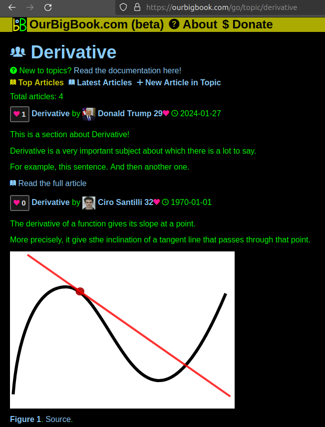
Figure 1. Screenshot of the "Derivative" topic page. View it live at: ourbigbook.com/go/topic/derivativeVideo 2. OurBigBook Web topics demo. Source. - local editing: you can store all your personal knowledge base content locally in a plaintext markup format that can be edited locally and published either:This way you can be sure that even if OurBigBook.com were to go down one day (which we have no plans to do as it is quite cheap to host!), your content will still be perfectly readable as a static site.
- to OurBigBook.com to get awesome multi-user features like topics and likes
- as HTML files to a static website, which you can host yourself for free on many external providers like GitHub Pages, and remain in full control
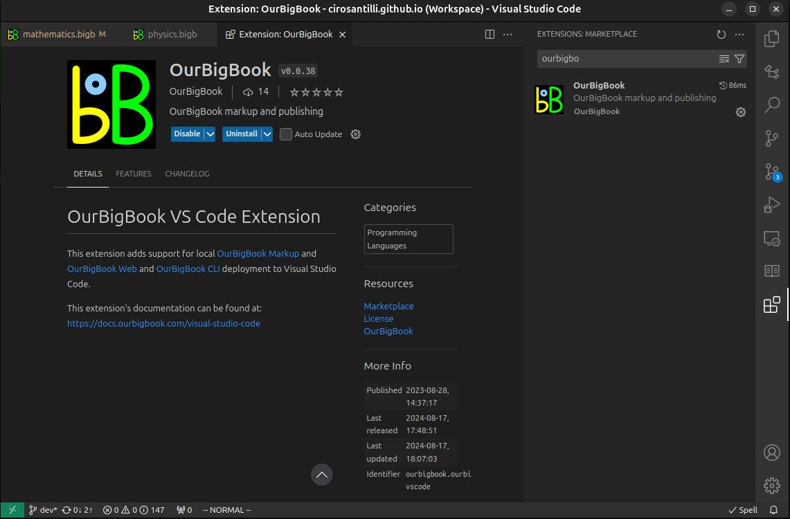
Figure 3. Visual Studio Code extension installation.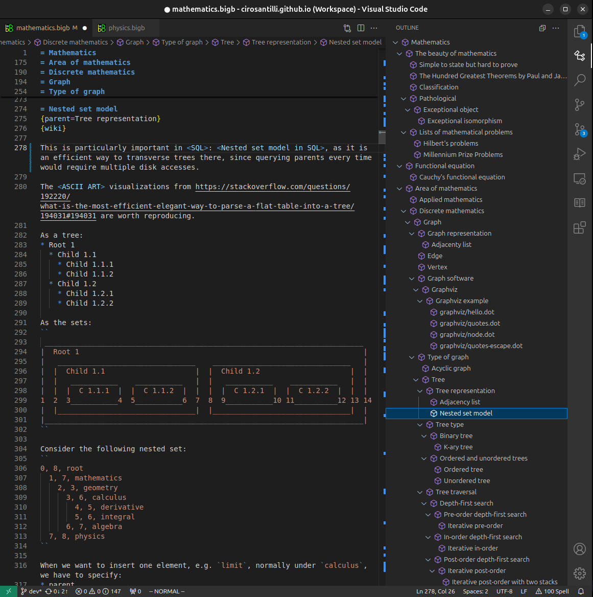
Figure 4. Visual Studio Code extension tree navigation.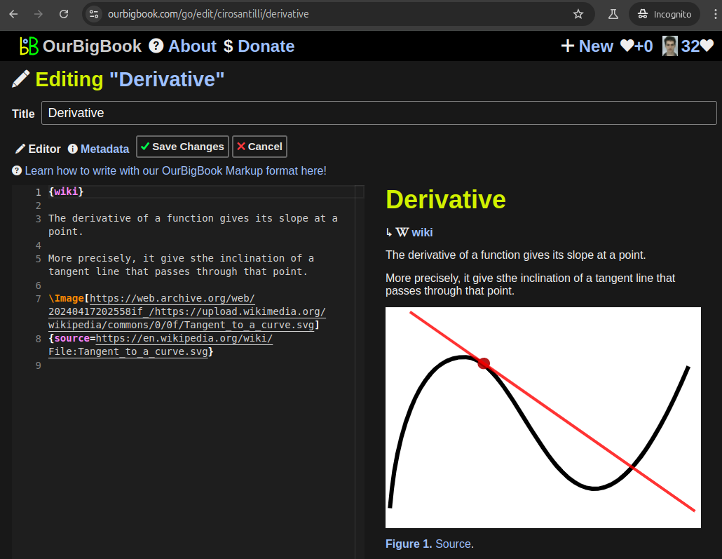
Figure 5. Web editor. You can also edit articles on the Web editor without installing anything locally.Video 3. Edit locally and publish demo. Source. This shows editing OurBigBook Markup and publishing it using the Visual Studio Code extension.Video 4. OurBigBook Visual Studio Code extension editing and navigation demo. Source. 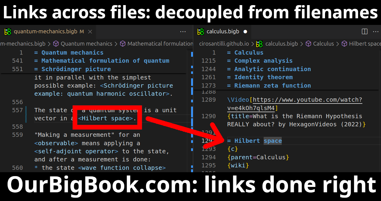
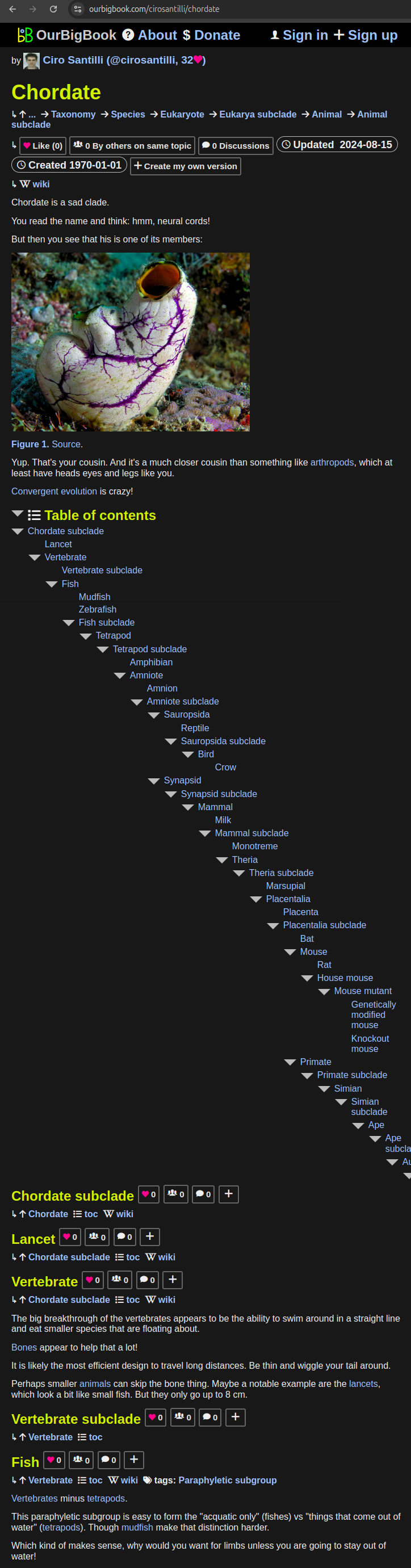
- Infinitely deep tables of contents:

All our software is open source and hosted at: github.com/ourbigbook/ourbigbook
Further documentation can be found at: docs.ourbigbook.com
Feel free to reach our to us for any help or suggestions: docs.ourbigbook.com/#contact