Topics (384k) Articles (398k) Users (410) Discussions (242) Comments (383) Files (13k) New article

A detection time gate is a selected interval during which a photodetector's output contributes to a measurement. Its start delay and duration are measured relative to a trigger or another time reference. The gate may control an integrating amplifier, an electronic counter or a software selection of recorded events; it need not physically switch off the light.
A gated integrator supplies a concrete apparatus. Stanford Research Systems' SR250 uses a triggerable gate generator, a fast integrator and a readout normalized by gate width. Its gate monitor can be displayed alongside the signal on an oscilloscope to check their relative timing.[ref] An integrated area and a gate-averaged amplitude are different output quantities: dividing an area by changes its units.
An original photon counting example shows the gate-width tradeoff. Suppose an ideal decaying signal has expected count rate for , and a constant background has rate . A gate from0 to collects expected countsIf signal and background counts are independent Poisson distributions and the background mean is known exactly, the background-corrected count has variance . Its signal-to-noise ratio is . With chosen values and , a gate of width gives about63.2signal counts,100background counts and ratio4.95. A gate of width collects95.0signal counts but300background counts, reducing that ratio to4.78. More collected signal alone does not guarantee a better measurement.
This example assumes ideal event registration; detector dead time, non-Poisson backgrounds or an estimated rather than known background alter the calculation. Gate timing jitter can also vary the admitted part of a rapidly changing signal. Gate placement and duration should therefore be checked against the actual waveform, background and measurement objective, rather than chosen solely from the nominal pulse width.
A detector linearity test checks whether changes in a detector's output remain proportional to changes in its incident signal over a stated operating range. For a photodetector with a fixed wavelength, geometry and readout gain, a linear response model iswhere is radiant power, is the baseline and is the appropriate response coefficient. A detector baseline subtraction removes the offset before comparing with . Linearity concerns the shape of that relation; an incorrectly calibrated constant can still give a linear detector.
A documented apparatus uses a beam splitter to illuminate two photodiodes at approximately a ten-to-one intensity ratio. NIST's measurement at compared responsivity with its low-power value, with the aperture filled and uniformly irradiated. The report explicitly notes dependence on irradiation geometry.[ref]
Spectroradiometric Detector Measurements: Ultraviolet, Visible, and Near-Infrared Detectors for Spectral Power by Thomas C. Larason and others. §9.1, printed pp. 85–86 and Figure 9.2
A detector's response to a small concentrated spot need not reproduce its response to the same total power spread over the aperture.For an original numerical example, stipulate baseline-corrected electric currents of , and at input powers , and . Normalizing the apparent spectral responsivity to the first point givesThe last point has three percent less response per unit power than the first. A straight line through the origin with slope would predict there instead of .
A useful test varies incident power while monitoring source stability and holding the beam position, illuminated area and electronic settings fixed. Record blocked-beam readings as well as illuminated readings. A residual that exceeds the combined measurement uncertainty identifies a departure from the tested model; it does not by itself locate the cause in the photodiode rather than an amplifier or other readout stage.
For pulses, average power alone may hide a nonlinear response to high peak power. A continuous-illumination test therefore does not automatically validate pulse energy measurement with a photodiode at a different pulse duration or spot size. Test the illumination and electrical range actually used, and distinguish a change in slope from a change in baseline.
A photoconductor is a detector whose illuminated material changes electrical conductivity, allowing an external circuit to measure the change under applied bias. It uses photoconductivity: absorbed photons can produce mobile electrons and electron holes, changing the conductive path between contacts. A simple photoresistor reads this as a light-dependent resistance. Shimadzu’s primary description explains band-gap excitation and the resistance decrease in a PbS detector.[ref]
How does a PbS photoconductive detector work? by Shimadzu Scientific Instruments. operating-principle paragraphs, band excitation and external readout
An original uniform-bar model makes the signal mechanism quantitative. Let the contact separation be , the conducting area , electron and hole number densities , and their mobilities . In the low-field ohmic model,Here is the positive elementary charge and the actual detector electric potential difference. If illumination changes carrier densities while mobilities stay fixed,The assumptions exclude contact barriers, strongly nonuniform illumination and a bias changed by the readout; those effects require an expanded model.
For , , , and , the conductivity increment is about . At fixed , the predicted current increment is about . These stipulated parameters illustrate the conversion of extra carriers into a signal, rather than specifications of a named detector.
Readout loading can change that result. In a divider powered at , with detector resistance in series with load , the output across the load isFor and , changing from to raises the output from about to . The detector’s own bias falls from about to . A light-dependent conductance and a measured divider voltage therefore need not have the same linearity. Record the actual bias and illuminated area when measuring spectral responsivity.
Photoconductor response time also depends on carrier storage and loss. A simple spatially uniform excess-carrier model is . After a step to constant generation , initially zero excess density becomes . Small sinusoidal modulation has response proportional to . With stipulated , the single-pole cutoff is about . Real traps, contacts and electronic filters need not yield one such time constant.
A proposed characterization biases the detector through a known readout, measures dark and illuminated currents at controlled wavelength and temperature, then chops or modulates the light and measures amplitude and phase versus modulation frequency. Repeat at several powers and biases to separate detector behavior from circuit loading. Temperature control matters: the manufacturer notes that PbS spectral sensitivity, response speed and dark resistance all change with temperature.[ref]
How does a PbS photoconductive detector work? by Shimadzu Scientific Instruments. temperature-dependence paragraph
The name photoconductive mode for a reverse-biased photodiode describes an operating choice of a junction detector; it does not make every such device the bulk-resistance detector modeled above. Likewise, a detector’s signal increase is not by itself a claim of unlimited useful gain: background response, dark current, noise, saturation and response time remain distinct characterization questions.
A phosphorothioate diastereomer is a stereochemical form of a phosphorothioate substitution that differs in configuration without changing connectivity. In a nucleic-acid phosphate joining different nucleotide environments, replacing a non-bridging oxygen with sulfur can make phosphorus a stereogenic center. The resulting and forms have the same elemental composition but a different spatial arrangement at that center.
They are diastereomers in the usual nucleic-acid context because the rest of the RNA already contains fixed stereochemistry, including its ribose units. Changing one phosphorus configuration while preserving those other centers does not produce the mirror image of the entire RNA. It is therefore misleading to call such a pair enantiomers merely because one phosphorus label changes from R to S. Assignment of the labels uses the Cahn-Ingold-Prelog priority rules, not the order in which a nucleotide sequence is written.
Two independently stereogenic substituted phosphates give four combinations: , , and . Their molecular masses are the same. A mass measurement alone cannot determine either the configuration at one site or the proportions in an unresolved mixture.
A simple activity model shows why mixture composition can matter. Suppose equal amounts of two purified forms separately give product fractions and in a stipulated assay. If molecules act independently and the assay response is linear, a mixture containing fraction of the first form gives . At , . These invented numbers illustrate averaging; competition for limiting components can invalidate that model.
The U6 metal rescue experiment supplies an actual chemical distinction. Sulfur substitutions with opposite phosphorus configurations at the same U6 position showed differing metal-rescue behavior, including differences between branching and exon ligation.[ref]
RNA catalyses nuclear pre-mRNA splicing by Sebastian M. Fica and others. Figure2, U80 substitution configurations and separate branching/ligation assays, pp.229–230.
Position, configuration and measured reaction therefore belong in the description of a phosphorothioate reagent.A root mean square phasor represents a single-frequency sinusoid by a complex amplitude whose magnitude is its root mean square value. With the convention and , defineIndeed, the period average of is , so . The factor in reconstruction distinguishes this convention from the peak-amplitude phasor convention in the parent article. The DOE handbook derives the same effective value by comparing the heating from alternating current and direct current.[ref]
Using RMS phasors for both electric potential difference and electric current, the passive-sign convention gives complex electrical powerTo see the normalization directly, multiplying the two reconstructed sinusoids and averaging over a period leaves . Peak-amplitude phasors would instead require the prefactor . This peak-versus-RMS normalization in complex electrical power must be stated before combining a source model with measured amplitudes.
For an original example, let and . The electric current lags the electric potential difference by , givingThe corresponding time-domain peaks are and . Treating those peaks as RMS phasor magnitudes would falsely double the computed complex electrical power. This representation assumes a sinusoid at one common frequency; a nonsinusoidal signal can have a root mean square value without being represented by one RMS phasor.
A peak amplitude phasor is the complex amplitude that reconstructs a real single-frequency sinusoid without an extra amplitude multiplier:Its modulus is the sinusoid's peak amplitude, and its complex argument is the wave phase relative to the chosen cosine reference. This is the default convention in phasor. MIT's sinusoidal notes explicitly describe the cosine reference and phase/amplitude parameters.[ref]
For an original example, take volts. Expanding the real part shows that volts, with peak amplitude volts and wave phase . The corresponding root mean square phasor is volts, whose magnitude is about volts. The physical signal is the same under both conventions.
The peak phasor versus positive-frequency Fourier coefficient distinction follows fromThus the positive-frequency coefficient in this two-exponential expansion is , not . A real sinusoid requires its conjugate negative-frequency term as well. This algebra does not assign ordinary Fourier-transform function values to an infinite-duration sinusoid; those require the corresponding distributional interpretation.
A common time-origin change multiplies both voltage and current peak phasors by the same unit-modulus factor, leaving their relative phase and impedance ratio unchanged. Peak-versus-RMS normalization in complex electrical power is still essential when an amplitude convention changes rather than just the time origin.
The exocarp is the outermost region of the pericarp. It forms the external covering of the fruit wall, outside the mesocarp and endocarp. The skin of a peach illustrates the term.[ref]
The exocarp belongs to the fruit, whereas the seed coat belongs to the enclosed seed. They may both act as protective coverings, but function alone does not make them the same structure. In a caryopsis their close attachment can conceal the distinction; tracing their origins to ovary and ovule respectively preserves it.
The mesocarp is the middle region of the pericarp, between the outer exocarp and inner endocarp. In a peach, much of the juicy edible flesh is mesocarp, while the stone is hardened endocarp.[ref]
Its name describes anatomical position rather than edibility or a fixed degree of softness. A useful dissection follows the layers from the surface inward before assigning names. This prevents the everyday category “flesh” from replacing the developmental distinction between fruit tissue derived from the ovary and the seed derived from an ovule.
The endocarp is the innermost region of the pericarp, the wall of a fruit. It lies inward of the mesocarp and surrounds the space containing the seeds. In a drupe such as a peach, the endocarp hardens into the stone.[ref]
The prefix specifies position, not one universal material. A hard endocarp is characteristic of a drupe, but naming an inner fruit-wall layer does not require every fruit to possess a stone. Following the tissue from the ovary into the mature fruit distinguishes endocarp from the seed coat inside it.
Pinned article: Introduction to the OurBigBook Project
Welcome to the OurBigBook Project! Our goal is to create the perfect publishing platform for STEM subjects, and get university-level students to write the best free STEM tutorials ever.
Everyone is welcome to create an account and play with the site: ourbigbook.com/go/register. We belive that students themselves can write amazing tutorials, but teachers are welcome too. You can write about anything you want, it doesn't have to be STEM or even educational. Silly test content is very welcome and you won't be penalized in any way. Just keep it legal!
Intro to OurBigBook
. Source. We have two killer features:
- topics: topics group articles by different users with the same title, e.g. here is the topic for the "Fundamental Theorem of Calculus" ourbigbook.com/go/topic/fundamental-theorem-of-calculusArticles of different users are sorted by upvote within each article page. This feature is a bit like:
- a Wikipedia where each user can have their own version of each article
- a Q&A website like Stack Overflow, where multiple people can give their views on a given topic, and the best ones are sorted by upvote. Except you don't need to wait for someone to ask first, and any topic goes, no matter how narrow or broad
This feature makes it possible for readers to find better explanations of any topic created by other writers. And it allows writers to create an explanation in a place that readers might actually find it.
Figure 1. Screenshot of the "Derivative" topic page. View it live at: ourbigbook.com/go/topic/derivativeVideo 2. OurBigBook Web topics demo. Source. - local editing: you can store all your personal knowledge base content locally in a plaintext markup format that can be edited locally and published either:This way you can be sure that even if OurBigBook.com were to go down one day (which we have no plans to do as it is quite cheap to host!), your content will still be perfectly readable as a static site.
- to OurBigBook.com to get awesome multi-user features like topics and likes
- as HTML files to a static website, which you can host yourself for free on many external providers like GitHub Pages, and remain in full control

Figure 2. You can publish local OurBigBook lightweight markup files to either OurBigBook.com or as a static website.
Figure 3. Visual Studio Code extension installation.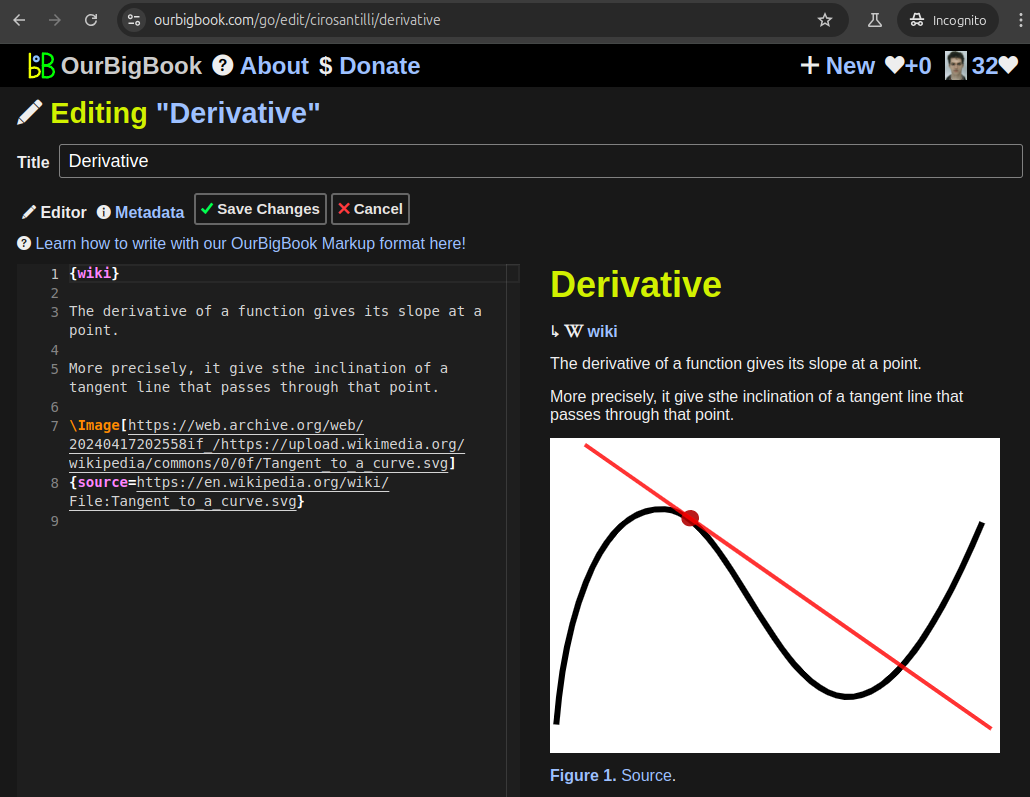
Figure 5. . You can also edit articles on the Web editor without installing anything locally. Video 3. Edit locally and publish demo. Source. This shows editing OurBigBook Markup and publishing it using the Visual Studio Code extension. 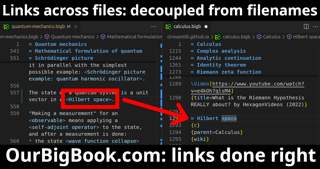
- Infinitely deep tables of contents:
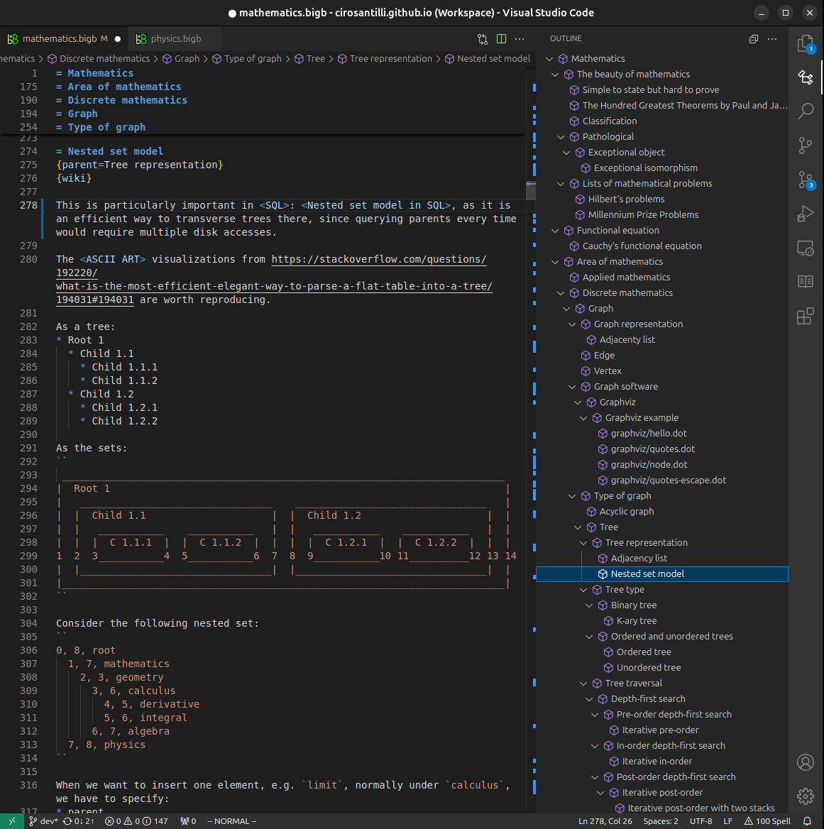

All our software is open source and hosted at: github.com/ourbigbook/ourbigbook
Further documentation can be found at: docs.ourbigbook.com
Feel free to reach our to us for any help or suggestions: docs.ourbigbook.com/#contact