A heart valve permits predominantly one-way blood flow through the heart. Leaflet motion follows changing pressure differences and structural constraints. The four main human valves occupy different chamber or outflow boundaries, so valve dysfunction has location-specific consequences.[ref]
Coaptation is the meeting and contact of opposing valve leaflet surfaces that helps a heart valve close. It is a geometrical and contact mechanics condition, distinct from the opening size, leaflet length or a single chordal tension measurement. The resulting contact region can be described by its location and coaptation area.
An original one-dimensional coverage model makes the role of support geometry clear. Let two opposing leaflets each reach a distance across an opening of width . A nominal overlap margin isWith mm and mm, the margin is 2 mm. If the opening widens to 34 mm with unchanged reach, the margin becomes mm, representing a gap in this simplified model. Actual leaflet contact also depends on three-dimensional orientation, deformation and loading, so positive overlap in a drawing is not sufficient proof of a seal.
A primary left-heart simulator study compared flat and saddle-shaped attachment boundaries in eleven human specimens of the mitral valve. Changes in cardiac valve annulus shape redistributed chordae tendineae forces; the tested shape comparison did not produce a statistically significant change in regurgitant volume.[ref]
Effects of a saddle shaped annulus on mitral valve function and chordal force distribution: an in vitro study by Jorge Hernan Jimenez and others. Abstract, Methods and Results
Geometry, attachment forces and leakage were related but separately observed quantities.This explains why a successful-looking contact region in one image need not specify the total backward blood flow. A narrow unobserved gap elsewhere may matter, while a contact outline supplies no direct measurement of its fluid transport. Conversely, measuring one chord's tension does not establish the contact state over every leaflet surface. A clear description of coaptation therefore identifies the valve, imaging phase and contact measure being discussed.
Coaptation area is the area of the contact region formed when opposing valve leaflet surfaces meet during coaptation. The measurement must specify the valve, phase and surface convention. Counting the same interface once is different from summing the apposed faces of both leaflets, and a projected image area is different from the area measured along a curved surface.
A primary investigation examined quantitative assessment of mitral coaptation using three-dimensional transesophageal echocardiography.[ref]
Quantitative assessment of mitral valve coaptation using three-dimensional transesophageal echocardiography by Frederick C. Cobey and others. Title and indexed Abstract, three-dimensional coaptation-zone assessment
This provides an experimental context for defining the zone before assigning it one scalar area. The observed or reconstructed leaflet geometry remains part of the measurement.For a specified contact patch on one reference face,If a planar patch is viewed at angle between its normal and the viewing direction, its projected area is . A true area of 20 mm viewed at therefore projects to 10 mm. This is an original geometrical example, not an echo calibration rule for all curved leaflets.
Area also omits the arrangement of the contact. In an ideal 10 mm by 10 mm gap map, a 10-by-2 mm contact strip spanning the full width has the same area as a 2-by-10 mm strip running along its height. If flow is constrained to travel from the bottom edge to the top edge within this two-dimensional map, the first strip blocks every path while the second leaves open side paths. Both contact areas are 20 mm.
Real valves have three-dimensional fluid gaps, deformation and changing pressure. The map is a counterexample to inferring closure from area alone, not a prediction of leakage magnitude. The location of contact, any remaining connected gaps and the surrounding heart valve mechanics matter alongside the reported coaptation area.
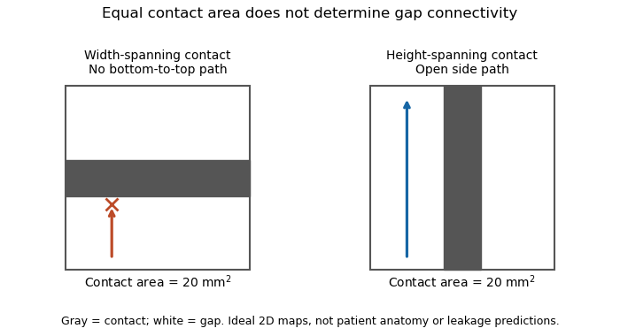
Equal coaptation area need not determine gap connectivity
. Original ideal two-dimensional contact maps. Each 10 mm square has a 20 square-millimetre contact strip. With paths confined inside the map, the horizontal strip blocks bottom-to-top passage, while the vertical strip leaves side paths. This illustrates geometric information lost by a scalar area, not measured valve leakage or patient anatomy. Details.
The mitral coaptation index is a dimensionless normalization of the mitral valve's coaptation area. In the primary method of Frederick C. Cobey and colleagues, it is the three-dimensional end-systolic coaptation-zone area divided by the three-dimensional mitral-valve area used in that protocol:The denominator and surface-reconstruction convention are part of the definition.[ref]
The study used intraoperative transesophageal echocardiography in 25 patients with functional mitral regurgitation, followed by offline analysis of the end-systolic geometry.[ref]
Quantitative assessment of mitral valve coaptation using three-dimensional transesophageal echocardiography by Frederick C. Cobey and others. Abstract, Methods
This supplies an experimental acquisition context for the ratio; it does not make every area called annular area interchangeable with the protocol's valve-area measurement.An original normalization example uses cm and cm, giving . A second constructed valve with areas 3 and 20 cm has the same index despite twice the absolute contact area. Conversely, keeping contact area 1.5 cm while changing the denominator to 15 cm gives . Absolute area and normalized coverage answer different questions.
Uniformly scaling every length by a positive factor multiplies both areas by , leaving unchanged. Inconsistent surface conventions do not cancel: counting two apposed faces in the numerator while counting their interface once in another reconstruction can change the ratio without a biological change.
Finally, the index does not describe the connectivity of any remaining gaps. Two contact patches with equal coaptation area and equal denominator can have different shapes and positions, as illustrated under coaptation area. The mitral coaptation index is a geometric descriptor to interpret alongside the reconstructed valve and blood flow, rather than a complete description of valve sealing.
A cardiac valve annulus is the supporting attachment region around a heart valve's opening, used as an anatomical and imaging reference for its valve leaflets. The term should be interpreted for the particular valve: the mitral annulus and the operational reference geometry of the aortic annulus are not interchangeable structures. An annulus is not necessarily a rigid, flat circle.
The three-dimensional shape matters experimentally. A primary study mounted eleven human specimens of the mitral valve in a left-heart simulator with adjustable flat or saddle-shaped annular configurations. In selected experiments, transducers recorded chordae tendineae forces.[ref]
Effects of a saddle shaped annulus on mitral valve function and chordal force distribution: an in vitro study by Jorge Hernan Jimenez and others. Abstract, Methods
The shape comparison redistributed chordal forces, showing that a two-dimensional diameter alone does not describe the full supporting geometry.An original area example separates two common geometric descriptors. An ellipse with semiaxes mm and mm has area mm. A circle of radius mm has the same area, but its diameter is about 28.3 mm rather than the ellipse's 40 mm major diameter. An equal area therefore does not determine the width a leaflet must span in every direction.
A further three-dimensional model can retain the same projected outline while varying attachment heights:Changing leaves the projected ellipse unchanged but changes the spatial boundary. This is a schematic saddle-like curve, not a complete anatomical model. It illustrates why measurements of projected area, diameter and height can carry different information. The relation between annular geometry, leaflet deformation and coaptation must be assessed with consistent valve-specific landmarks and phases.
The aortic annulus is an anatomical or operational reference associated with attachment of the aortic valve leaflets at the base of the aortic root. The term requires a convention. The three-dimensional semilunar leaflet attachment lines form a crown-like arrangement; they are not simply one flat circular line of tissue. An expert anatomical account explicitly distinguishes these attachments from the junction between ventricular and arterial walls.[ref]
The surgical anatomy of the aortic root by Robert H. Anderson. Abstract, semilunar attachments and ventriculo-aortic junction
For an explicitly defined geometric measurement, one can construct a virtual basal ring from basal leaflet-attachment landmarks. Such a reference plane and its enclosed outline should not be silently identified with the entire crown-shaped attachment path. The sinotubular junction is a different, more distal boundary of the aortic root.
An original area calculation explains why a reported diameter also needs a definition. Suppose the chosen reference outline is an ellipse with semiaxes mm and mm. Its area is mm, while its largest and smallest diameters are 28 and 20 mm. The diameter of an equal-area circle isThe three numbers describe different features of the same outline. Selecting one two-dimensional chord does not determine its entire area or the spatial leaflet attachments.
This is a geometry example, not a device-sizing recommendation. An imaging account should identify the landmarks, reference plane, phase of the cardiac cycle and reported descriptor. Those choices connect a measured outline to a reproducible anatomical question; they do not turn every structure called annulus into the same physical ring.
The virtual basal ring is the geometric reference formed from the lowest attachment points of the three aortic valve leaflets. It specifies a basal plane of the aortic root; it is not the entire crown-shaped tissue attachment represented by the anatomical aortic annulus.[ref]
Surgical anatomy of the aortic valve and root—implications for valve repair by Ruggero De Paulis and Andrea Salica. General considerations; Figures 1–2, basal landmarks and crown-shaped leaflet attachment
Three noncollinear landmarks determine a plane. For landmark position vectors , a normal isThe reference plane then obeys . Near-collinear landmarks make small, illustrating geometrically why landmark identification affects orientation. These equations construct a reference, not a ring of newly discovered tissue.
A plane alone also supplies no unique anatomical outline. Three points can define a circumcircle, but choosing that circle is a modeling convention; the actual lumen outline in that plane can be noncircular. For an original ellipse with semiaxes 15 and 10 mm, the enclosed area is mm and the equal-area circular diameter is mm. Neither the 30 mm major diameter nor the 20 mm minor diameter equals that number.
The virtual basal ring is useful because it gives different images a specified basal reference. A measurement must still identify its landmarks, outline, cardiac cycle phase and diameter or area convention. It should not silently substitute the sinotubular junction or the longer three-dimensional leaflet attachment path for this basal reference.
The mitral annulus is the supporting attachment region around the mitral valve between the left atrium and left ventricle. It supplies a reference for the valve leaflets but is not adequately described as a rigid, flat circle. Its spatial shape and motion form part of the coupled valve apparatus.
A primary left-heart simulator study compared flat and saddle-shaped annular configurations in eleven human valve specimens. The investigators measured chordae tendineae forces in selected experiments and found a redistribution of those forces with annular shape.[ref]
Effects of a saddle shaped annulus on mitral valve function and chordal force distribution: an in vitro study by Jorge Hernan Jimenez and others. Abstract, Methods and Results
This tests a geometrical variable directly rather than assuming that one diameter captures the complete attachment boundary.An original circular approximation illustrates why fractional diameter and area changes differ. If a hypothetical ring's diameter changes from to , its planar area changes from to . A diameter decrease gives a area decrease in this model. The equation is not a claim that the native mitral annulus is circular or planar.
Motion adds another geometrical contribution. In a rigid-piston model, translation of a boundary with area by distance changes the represented volume by . Stipulated values 10 cm and 0.4 cm give 4 mL. Actual mitral annular excursion occurs in a deforming heart, so this does not assign all stroke volume to one translating plane.
Annular area, shape, position and leaflet coaptation are therefore related but distinct observations. Comparisons need consistent landmarks and phases, while models must specify which parts of the surrounding apparatus are allowed to move.
Mitral annular excursion is displacement of the mitral annulus over a specified part of the cardiac cycle. A commonly used longitudinal observation follows an annular landmark along the cardiac long axis during ventricular systole. The reference position, direction and endpoints are part of the measurement; displacement is distinct from annular area or leaflet coaptation.
The measurement question can be written explicitly. For a fixed unit axis and landmark position , defineAn original 10 mm displacement viewed along an axis tilted by projects to mm. Thus changing the observation direction changes the reported excursion even for the same motion. A single landmark also need not represent every part of a deforming mitral annulus.
A primary human study used cine magnetic resonance imaging, measuring longitudinal displacement in long-axis views and stroke volume in short-axis views. Its model combined displacement with a ventricular short-axis area.[ref]
Atrioventricular plane displacement is the major contributor to left ventricular pumping in healthy adults, athletes, and patients with dilated cardiomyopathy by Marcus Carlsson and others. Abstract, Methods
In an original rigid-piston approximation, area moving axially by sweeps volume . Areas 20 and 40 cm paired with displacements 1 and 0.5 cm both give 20 mL. Smaller excursion need not imply a smaller geometric swept volume when area differs; this model area is not automatically the mitral opening area.A complementary experiment by C. Carlhäll and colleagues implanted markers around the mitral annulus and ventricular wall in six sheep. Biplane fluoroscopy reconstructed three-dimensional marker motion, and tetrahedron-based estimates assessed annular contributions to filling while loading and contraction were varied.[ref]
Contribution of mitral annular dynamics to LV diastolic filling with alteration in preload and inotropic state by C. Carlhäll and others. Abstract, experimental methods
This connects a displacement measurement to moving-chamber geometry. The changing boundary, surrounding deformation and blood flow must be distinguished when relating mitral annular excursion to filling or ejection.A valve leaflet is a mobile tissue flap forming part of a heart valve. Its movement and contact with neighboring leaflets help permit forward blood flow while limiting backward flow. The supporting cardiac valve annulus, the pressure difference and the leaflet's geometry all contribute to its behavior. The meeting of leaflet surfaces that closes a valve is called coaptation.[ref]
The mitral valve and tricuspid valve have leaflets supported by chordae tendineae and papillary muscles. The aortic valve and pulmonary valve instead have pocket-like cusps without that chordal apparatus. A leaflet is therefore a functional part of a particular valve structure, not an isolated rigid door.
An original force estimate illustrates the loading scale. A uniform pressure difference over an effective area gives a resultant . For stipulated kPa and cm, N. Doubling the area at the same pressure doubles this resultant, but it does not specify how the load is divided among attachments or distributed as tissue stress.
A primary left-heart simulator experiment measured chordae tendineae forces while moving papillary muscles and found responses that depended on the chordal type.[ref]
Effects of papillary muscle position on chordal force distribution: an in-vitro study by Jorge Hernan Jimenez and others. Abstract, Methods and Results
This gives a concrete reason to examine leaflet geometry and supporting connections together. Complete coaptation is a contact-and-motion condition; an accurate measurement of one chordal force does not by itself show that the entire valve seals.The mitral valve separates the left atrium from the left ventricle. In a reservoir model with the atrium incorporated into the venous filling compartment, ideal one-way flow is , where and is open-valve hydraulic resistance. The positive-part rule prevents reverse flow in this idealization.
Mitral regurgitation is backward blood flow from the left ventricle into the left atrium through the mitral valve during ventricular systole. Incomplete leaflet coaptation permits a second outflow route while ventricular pressure drives forward ejection through the aortic valve. The imaging framework distinguishes primary leaflet disease from secondary dysfunction associated with the surrounding ventricular apparatus.[ref]
Recommendations for Noninvasive Evaluation of Native Valvular Regurgitation by William A. Zoghbi and others. Section III, Mitral Regurgitation; III.B, primary and secondary mechanisms
An original volume balance separates total ventricular emptying from forward output. Suppose there is no other abnormal communication and no appreciable inlet flow during the chosen systolic interval. ThenFor stipulated total ejection 90 mL and forward aortic ejection 60 mL, the regurgitant volume is 30 mL and the regurgitant fraction relative to total ejection is . Reporting only the 90 mL volume change would not identify how much reached the forward outlet. The technical report describes this complementary ventricular-volume/aortic-flow approach.[ref]
Recommendations for Noninvasive Evaluation of Native Valvular Regurgitation by William A. Zoghbi and others. Figure 8, page 316; Section III.H.2
Backward volume also depends on duration, not just instantaneous speed. For a chosen outlet surface with normal directed toward the left atrium,This defines an integrated transport quantity. A short high-speed episode and a longer lower-speed episode can have the same integral, and a single peak velocity supplies neither surface area nor duration.
Consequently, leaflet anatomy, mitral coaptation index, regurgitant volume and chamber remodeling are distinct observations. Doppler echocardiography relates measured motion to flow, while anatomical imaging identifies the moving structures. Combining these measurements makes the question of leakage more precise than treating any one image dimension as a complete measure of mitral regurgitation.
The regurgitant fraction is the proportion of a valve-related total ejected blood volume that returns through the leaking valve. For the left ventricular balance used to assess mitral regurgitation, let be total ventricular stroke volume, the matched forward aortic volume and the regurgitant volume. With no other abnormal communication or confounding valve leak,The imaging recommendations use complementary volume and flow measurements to quantify these quantities.[ref]
Recommendations for Noninvasive Evaluation of Native Valvular Regurgitation by William A. Zoghbi and others. Section II.B.6, volumetric methods; Figure 8, p.316
An original example takes mL and mL. Then mL and RF is 30%. The quotient instead expresses leakage relative to forward delivery; it is not the same fraction. The denominator is part of the definition.
Equal fractions also need not indicate equal transported amounts. A 30 mL leak out of 100 mL and a 60 mL leak out of 200 mL both have RF 30%. Conversely, an unchanged 30 mL regurgitant volume gives RF 50% if total ejection falls to 60 mL. These stipulated cases isolate the normalization rather than assigning a clinical severity category.
The two measurements in a derived RF may share errors. For , first-order propagation givesThe covariance term should follow the actual acquisition and data reduction, rather than assuming independence because forward and total volume have different names.[ref]
RF is therefore a normalized transport quantity. A peak jet velocity, a valve image and ejection fraction provide other information; none supplies RF without the matching flow or volume model. Specify the valve, flow convention and acquisition interval when comparing measurements.
Regurgitant volume is the amount of blood transported backward through a leaking heart valve over a specified interval, usually a cardiac cycle. In mitral regurgitation, it is backward transport from the left ventricle towards the left atrium during ventricular systole. It measures an integrated volume rather than a peak velocity or one still image of the jet.
For a fixed measurement surface with normal pointing in the backward direction, the instantaneous backward flux is the surface integral of the corresponding positive normal velocity. Integrating over time givesA moving surface instead requires velocity relative to that surface. This convention separates material transported through a boundary from the motion of the boundary itself.
An imaging estimator combines an effective regurgitant orifice area with a velocity-time integral. If the effective area is approximately constant over the interval,The technical recommendations describe this area-times-integrated-velocity approach and complementary volumetric methods.[ref]
For stipulated and VTI 150 cm, the estimate is mL. Equal peak velocities do not ensure equal VTI: two triangular velocity pulses of height 5 m/s and durations 0.10 and 0.20 s have integrals 25 and 50 cm. At the same effective area, their modeled backward volumes are 5 and 10 mL. These are illustrative pulses, not observed valve measurements.
A changing effective area cannot generally be pulled out of the time integral. A peak-area measurement multiplied by the full VTI can therefore answer a different question from integrating the changing area and velocity together. Independently, the ventricular balance requires compatible total and forward stroke volumes. The regurgitant fraction then divides by the relevant total volume; it does not replace the underlying amount measurement.
The effective regurgitant orifice area is a flow-equivalent area for a leaking heart valve: the instantaneous backward volume flow rate divided by the corresponding jet speed ,It characterizes the effective stream passing through the leak. It need not equal the anatomical opening traced on an image, because flow contracts and its velocity is not uniform across every geometric surface. The vena contracta and the upstream convergence pattern provide complementary flow information.[ref]
The proximal isovelocity surface area method illustrates how an area can be inferred without drawing the hole itself. Color Doppler identifies an upstream surface at a selected aliasing speed . In an ideal hemispherical convergence model of radius , conservation of mass givesContinuous-wave Doppler echocardiography supplies the jet speed. The convergence radius and jet speed must refer to matching times. The hemisphere is an assumption about flow geometry, not a property guaranteed by the instrument.[ref]
For an original model calculation, let cm, cm/s and cm/s. Then mL/s and . At otherwise fixed inputs a ten-percent radius overestimate multiplies the inferred area by . The radius-squared dependence explains why a small geometric measurement error can matter substantially.
An instantaneous effective area and an integrated regurgitant volume answer different questions:If the effective area is constant, this becomes using the velocity-time integral. A stipulated VTI of 150 cm with the calculated constant area gives 36.19 mL. A single peak area generally cannot be pulled outside the integral when the leak changes during systole. Alternatively, defines a velocity-weighted mean effective area over that interval. The technical report explicitly distinguishes instantaneous convergence measurements from temporally varying regurgitation.[ref]
Recommendations for Noninvasive Evaluation of Native Valvular Regurgitation by William A. Zoghbi and others. Section II.B.6.c, timing and duration of regurgitation, pp. 312–313
The proximal isovelocity surface area method estimates instantaneous flow towards a leaking heart valve from the upstream convergence field. Color Doppler supplies a contour at a chosen aliasing speed . If that contour represents a hemisphere of radius , flow approximately normal to it giveswhere the matched jet speed comes from continuous-wave Doppler echocardiography. The inferred effective regurgitant orifice area is a flow-equivalent area, not the area of the colored region or necessarily the anatomical hole.[ref]
The physical idea is conservation of mass. More generally, . Replacing that integral by one speed times a surface area requires an appropriate velocity component and geometry. Doppler ultrasound measures a component along the beam, so an apparent constant-color contour is not automatically a measured three-dimensional surface of constant normal speed.
For an original hemispherical example, let cm and cm/s. The modeled backward flow is mL/s. With matched cm/s, the effective area is . If this area remains constant and the velocity-time integral is 140 cm, the modeled regurgitant volume is 25.33 mL. These are stipulated inputs, not severity thresholds.
Geometry and timing can each change that inference. In an ideal radial model restricted to a known solid angle , ; a hemisphere uses . Thus a stipulated gives half the flow at the same radius and speed. This illustrates flow-convergence angle correction; a real nonhemispherical or confined flow needs a justified geometric model rather than an arbitrary numerical adjustment.
Likewise, a radius observed at one instant must be paired with the jet speed at that instant. A peak effective area multiplied by a full-cycle velocity integral can overstate transported volume when the leak occupies only part of systole. The technical report explicitly discusses matching times, nonplanar convergence and changing regurgitant duration.[ref]
Recommendations for Noninvasive Evaluation of Native Valvular Regurgitation by William A. Zoghbi and others. Section II.B.6.c, pp. 312–313, timing, duration and shape qualifications
The apparatus observes an aliased velocity pattern and a jet spectrum; the flow and area are derived through the stated model.Flow-convergence angle correction replaces the hemispherical collection area assumed by the proximal isovelocity surface area method with an area justified by the actual convergence geometry. If flow is radial and has constant normal speed on a spherical surface of radius spanning solid angle , thenThe correction concerns a flow surface, not simply the apparent opening of a heart valve in one image. The technical recommendations explicitly distinguish a nonplanar valve surface, persistent flow constraints and nonhemispherical contours.[ref]
An original geometry comparison shows why a planar angle is insufficient without a three-dimensional model. A spherical cap within a cone of half-angle hasFor , this gives , or half a hemisphere. A different model that retains a fraction of the azimuthal extent of a hemisphere gives a fraction proportional to that azimuthal angle. A measured angle must therefore be identified as a polar cone angle, an azimuthal sector or another geometric quantity before selecting a formula.
Using the stipulated spherical-cap model with cm and cm/s gives mL/s, whereas a full hemisphere at the same radius and speed gives 90.48 mL/s. With a matched jet speed of 500 cm/s, the corresponding effective regurgitant orifice area estimates are and . These numbers illustrate geometry, not a correction prescribed for an observed valve.
The velocity measurement adds a separate limitation. Color Doppler measures a beam-directed velocity component; a constant-color boundary need not be a sphere of constant normal flow speed. Changing the assumed collection area cannot repair an incorrectly measured radius, a nonuniform flow field or a jet velocity acquired at a different time.
The apparatus therefore provides an image and a velocity spectrum, while the corrected flow remains a model-based inference. The primary report discusses changing the aliasing contour to reduce constraint and states that a persistently unsuitable geometry may not support a simple angle correction.[ref]
Recommendations for Noninvasive Evaluation of Native Valvular Regurgitation by William A. Zoghbi and others. p. 313, constrained convergence and limits of reporting a corrected estimate
Articles by others on the same topic
There are currently no matching articles.