A gear train is an interconnected arrangement of gears that transmits rotation through one or more meshes. Its behavior depends on which gears mesh and which are rigidly attached to the same rotating body. A simple gear train passes motion through successive individual gears; a compound gear train uses at least one intermediate rotating body carrying different gears rigidly together.[ref]
For a chain of external meshes on fixed parallel axes, each mesh satisfies . Multiplication gives the overall signed gear ratio; two rigidly joined gears instead share exactly the same angular velocity. These are different connection rules and must not be interchanged.
In a simple gear train with tooth counts 16, 40 and 64, the overall relation isThe intermediate count cancels, and the two reversals give equal input/output rotation directions. That intermediate gear can still change spacing and mounting geometry even though it does not change this reduction ratio.
For a compound gear train, let a 16-tooth input drive a 48-tooth gear, rigidly joined to a 12-tooth gear that drives a 60-tooth output. ThenAn input of revolutions per minute produces revolutions per minute at the output. The two intermediate tooth counts do not cancel because they belong to different gears sharing rotation, rather than one gear engaging both neighbors.
In steady operation, stage gear efficiencies multiply when all intervening losses are included in their stated power boundaries. If the two stages each have efficiency , the total is ; at input torque , the output torque is . These fixed-axis relations do not automatically describe arrangements whose gear axes move. In all cases, measured speeds test kinematics, while measured power is needed to establish losses.
A split-torque transmission divides transmitted load among two or more mechanical paths and subsequently combines their contributions. Its purpose is to let several meshes carry a total load that would otherwise pass through one path. The gear torque-path load fraction depends on compatibility, stiffness, gaps and mounting; a symmetric layout alone does not prove equal sharing.
For an original idealization, refer both branch torques to the same shaft coordinate and let their common elastic twist be . With torsional stiffnesses and no initial gaps,Values and under total torque give and branch torques and . If each branch were limited to , this sharing would limit total load to ; equal sharing would permit within the same simplified capacity assumptions.
Parallel-path gear efficiency also differs from the product rule for serial stages. If input power fractions are with , and each branch delivers fraction of its input power to the common output boundary, thenFor fractions and efficiencies , the result is . Multiplying the two branch efficiencies would describe a different arrangement of power boundaries.
The primary face-gear program reported input-pinion torque division about , while its two idlers shared about . These were measured results with stated calibration limitations, not exact consequences of the layout.[ref]
Development of Face Gear Technology for Industrial and Aerospace Power Transmission by Gregory F. Heath and others. Summary, printed p. iii; Conclusions, printed p. 84, torque splits and strain/load calibration limits
A meaningful load-sharing test measures both paths over relevant load and position ranges. Strain gauges need an appropriate measurement calibration because different tooth load distributions can produce different strain responses for the same transmitted load. Floating pinions provide one mechanism for reducing imbalance, but the complete assembly and its constraints still determine the operating split.
A gear torque-path load fraction specifies how a stated total transmitted torque is divided among paths of a split-torque transmission. With all branch torques referred to the same shaft coordinate,For positive total torque and nonnegative contributions, the fractions lie between zero and one and sum to one. If a path carries reverse or circulating power, the signed ratio requires a different interpretation; it need not lie in that interval.
The common coordinate is essential. Two branches carrying at and carry powers and . Their equal raw torques do not imply equal power shares. If ideal gearing brings both contributions to a common output speed , their output torques are and , giving fractions and .
For parallel elastic paths with the same twist coordinate and zero gaps, gives . In that model a stiffness ratio gives fractions and , regardless of the total torque while the same linear branches remain active. Gaps and a floating pinion can change that allocation.
A sensor ratio also needs a measurement model. If two channels obey and , thenEqual torques with sensitivities and give raw signals in the ratio ; the raw signal fraction is not the torque fraction . Cross-talk and changing tooth-load distributions may require a fuller calibration model.
The primary face-gear program reported approximately division at the input pinions and a different split between its idlers. The report also explains why tooth strain was not an invariant direct proxy for transmitted load.[ref]
Development of Face Gear Technology for Industrial and Aerospace Power Transmission by Gregory F. Heath and others. Section VIII, printed pp. 71–78; Conclusions, printed p. 84, torque calibration, reported splits and strain/load limitations
Report the reference shaft, sign convention, operating condition and measurement uncertainty with a torque-path fraction.A floating pinion has mounting freedom that permits a limited position adjustment between its mating meshes. The resulting force balance can improve load division in a split-torque transmission. Floating does not mean unsupported: bearing and shaft constraints still transmit loads, and the allowed displacement must match the intended balancing direction.
An original symmetric scalar model illustrates the mechanism. Let two opposed mesh reactions bewhere sets mean compression, represents an initial mismatch and is the pinion's balancing displacement. Assume both contacts remain compressed. Let floating-pinion centering stiffness provide support reaction , with the reaction sign chosen so that equilibrium is . ThenWith negligible centering restraint, and the reactions become equal. In the rigid-centering limit, and the original imbalance remains.
For stipulated , and , rigid centering gives forces and . Free adjustment gives and . At , displacement is and forces are and . These describe the chosen scalar model, rather than a complete face-gear support design.
The primary 2002 rig slow-rolled pinions between two face gears, applied loads through hanging masses, pulleys and cables, and used tooth-root strain gauges. Its cantilevered pinion mount allowed a balancing displacement.[ref]
Development of Face Gear Technology for Industrial and Aerospace Power Transmission by Gregory F. Heath and others. Summary, printed p. iii; Introduction, printed p. 1; Section VIII, torque calibration and split determination
The report's modified fixed-pinion comparison sent nearly all its load to one face-gear mesh, illustrating the effect of constraint in that tested assembly.[ref]Development of Face Gear Technology for Industrial and Aerospace Power Transmission by Gregory F. Heath and others. Conclusions, printed p. 84, fixed modified-idler comparison
Finite travel, friction, backlash or loss of one contact can prevent the ideal balancing solution. At low load, the condition that both model forces are nonnegative must be checked; a gear tooth engagement threshold can change the equations. Position freedom can help sharing without guaranteeing identical tooth stress or a perfectly equal torque split at every operating condition.
Floating-pinion centering stiffness describes the local restoring-force response of the mounting to displacement along a specified balancing coordinate. If mounting reaction is , a convenient positive restoring convention isFor , has force-per-length units. A rotational coordinate would require a torque-per-angle stiffness instead; the coordinate and displacement endpoints must be stated before comparing values.
In an original symmetric model of a floating pinion, two compressed mesh reactions obeyWith support reaction , equilibrium givesThe rigid-centering imbalance is , soBoth reactions must remain nonnegative for this two-contact model to apply.
For , and , choose . Displacement is and reactions are and . Raising to reduces displacement to but gives forces and . Stronger centering keeps the location closer to its reference while preserving more of the original imbalance.
Dynamic response is another question. With an effective mass and viscous coefficient , the same linearized floating-pinion balancing mode obeysIts undamped natural frequency is in angular-frequency units. A favorable static split does not by itself establish favorable dynamic behavior, and the toy mode does not include every shaft or housing motion.
A stiffness measurement should separate mounting reaction from the mesh reactions or report the combined assembly stiffness explicitly. The primary 2002 face-gear program used a cantilevered mounting to permit pinion balancing and examined a constrained comparison; it did not establish one universal centering stiffness for all transmissions.[ref]
Development of Face Gear Technology for Industrial and Aerospace Power Transmission by Gregory F. Heath and others. Introduction, printed p. 1; Conclusions, printed p. 84, floating mounting and modified fixed-pinion comparison
A floating-pinion balancing mode is a reduced mechanical motion in which a floating pinion shifts between mating meshes and redistributes their reactions. A one-coordinate model can connect the static balance set by floating-pinion centering stiffness with oscillation, damping and the possibility of losing a contact.
For two compressed linear contacts of stiffness , mismatch , support stiffness , effective mass and viscous damping coefficient , the illustrative equation isThe static position is . Setting givesFor , the oscillation frequency is and its amplitude envelope decays as . These frequencies have angular-frequency units; ordinary frequency is .
An original example uses , , and . It gives , , and an envelope reduced to after . With mismatch , the equilibrium displacement is . These are chosen model parameters, not measured gearbox constants.
A floating-pinion contact-loss check must still enforce the assumptions. For reactions and , both contacts remain compressed only while . If the oscillation leaves that interval, the two-contact linear equation must change; extrapolating a sinusoid into tensile tooth forces is inconsistent.
A motivating experiment perturbs the pinion slightly about a controlled loaded state, records its displacement and mesh-force proxies, and compares frequency and decay with the model while checking contact continuity. The primary face-gear report used slow rolling to study torque division and mounting freedom; it is evidence for that tested balancing arrangement, not a measurement of the hypothetical resonant frequency above.[ref]
Development of Face Gear Technology for Industrial and Aerospace Power Transmission by Gregory F. Heath and others. Introduction, printed pp. 1–2; test description and Conclusions, printed p. 84
A floating-pinion contact-loss check tests whether the motion predicted by a floating-pinion balancing mode remains compatible with every contact assumed to be compressed. It prevents a two-contact linear solution from being extrapolated into tensile tooth forces.
For the symmetric modelwith , mismatch , displacement and fixed mean approach , both contacts are compressed only whenAt equality one modeled force is zero. Outside the interval the linear expression makes one force negative; the unilateral model must replace that value by zero and the force-balance equations must be solved again.
Write and define the floating-pinion compression marginIf the motion satisfies , then is sufficient to retain both contacts. For a steady single sinusoid of amplitude and fixed , the maximum of over a complete cycle is , making the condition exact for that stipulated motion.
An original example uses , and . The margin is . A sinusoidal amplitude retains a minimum compression ; with , the smallest contact force is . Amplitude instead makes the unconstrained formula reach , revealing a contact-loss inconsistency rather than a physical tensile contact.
For a damped transient, an amplitude envelope is a sufficient bound but need not be attained at the phase where contact is least compressed. Failure of that sufficient envelope test therefore calls for examining the actual trajectory; it is not automatically proof that a real contact opened.
A controlled dynamic test can compare displacement with load-sensitive observations and check whether the assumed contact set persists. The historical face-gear program examined mounting freedom and torque division under slow rolling; it did not validate every possible dynamic contact assumption.[ref]
Development of Face Gear Technology for Industrial and Aerospace Power Transmission by Gregory F. Heath and others. Introduction, printed pp. 1–2; Conclusions, printed p. 84, floating versus constrained mounting
The floating-pinion compression margin is the amount of relative approach remaining before the less compressed contact reaches zero compression in a stated two-contact model. It turns the assumptions of a floating-pinion balancing mode into a quantitative admissibility check.
For and , let equilibrium position be and defineA positive means both contacts are compressed at equilibrium. If with , then guarantees compression throughout the bounded motion. For a steady single sinusoid and fixed , this is the exact full-cycle condition; a general transient envelope supplies only a sufficient bound.
An original nominal example has and , giving . A displacement amplitude passes that nominal check, leaving of minimum compression for the sinusoidal model.
A floating-pinion robust contact margin includes bounded parameter uncertainty. If and , a conservative lower margin isFor and , . The same amplitude is no longer guaranteed admissible, although failure of the bound does not prove contact loss. Amplitude leaves at least under these independent interval bounds.
In the symmetric static model, givesfor positive mesh stiffness and nonnegative floating-pinion centering stiffness . Mounting freedom can change the margin, but it also changes dynamics; maximizing this one scalar is not a complete gearbox design rule.
A floating-pinion contact-loss check must recompute the contact model once a force reaches zero. The historical face-gear tests provide evidence about mounting freedom and measured torque division under slow rolling, rather than a universal dynamic margin.[ref]
Development of Face Gear Technology for Industrial and Aerospace Power Transmission by Gregory F. Heath and others. Introduction, printed pp. 1–2; Conclusions, printed p. 84
A floating-pinion robust contact margin is the smallest two-contact compression margin allowed by a stated set of uncertain parameters. It strengthens a nominal floating-pinion compression margin by checking every admissible parameter combination, while retaining the assumptions of the underlying contact model.
Let be the common approach and the equilibrium imbalance in the symmetric linear model. If the admissible pairs form a set , defineFor displacement from equilibrium with , the smaller contact compression is at least . Thus guarantees positive compression for both contacts throughout the bounded motion. Equality permits zero compression and does not guarantee maintained compressive contact.
For independent interval bounds, or a bounding rectangle containing all possible pairs,This is exact when every pair in the rectangle is admissible. If the rectangle includes impossible combinations, it remains a conservative lower bound on .
A correlated floating-pinion uncertainty set can materially change the conclusion. In an original example, all quantities are in micrometres andHere stays positive, so for every allowed . The exact joint-set margin is . Treating the ranges independently instead gives . An amplitude passes the joint-set guarantee with residual compression , but fails the rectangular sufficient test. Failure of a conservative test does not itself demonstrate contact loss.
The admissible set must come from defensible parameter bounds, including any shared mounting or thermal effects. A covariance estimate alone supplies no absolute bound for all realizations. If the motion amplitude also depends on uncertain parameters, a direct bound on can preserve correlations that separate worst-case bounds discard.
Floating mounting was physically motivated by face-gear load sharing. NASA's primary report describes mounting freedom and slow-roll torque-division tests; those observations motivate the contact model, but do not validate every dynamic or uncertainty assumption above.[ref]
Development of Face Gear Technology for Industrial and Aerospace Power Transmission by Gregory F. Heath and others. Introduction, printed pp. 1–2; Conclusions, printed p. 84
Once a contact opens, a floating-pinion contact-loss check must use the appropriate changed force law.A floating-pinion affine uncertainty bound evaluates the minimum contact-compression margin when the approach and imbalance depend linearly plus a constant on bounded shared parameters. It gives an exact result for a box of uncertainty variables, while preserving the dependence those variables induce between physical quantities.
In the correlated floating-pinion uncertainty set, supposeAll uncertainty vectors in this box are assumed admissible. For the linear two-contact model, the floating-pinion robust contact margin is the infimum of over that box.
First resolve the absolute value:For any affine expression , its minimum is : choose each bounded variable with the sign opposing its coefficient. Applying this rule to the two branches givesThe branches can attain their minima at different parameter vectors. Taking the smaller of their independently attainable minima is valid; requiring both minima to occur at one vector would impose an unnecessary condition.
For an original example in micrometres, letThe two branch minima are and , so . The first is attained at . Treating the separate physical ranges independently instead gives and , hence a looser bound. A motion amplitude leaves guaranteed compression in the shared-variable model.
The result is exact for the stated box and affine model. Additional constraints can make it conservative; nonlinear parameter dependence or opening of a contact can invalidate the model itself. A floating-pinion ellipsoidal uncertainty bound addresses a different set shape, and a statistical covariance matrix alone does not certify a hard bound.
NASA's face-gear report supplies the physical motivation for examining mounting freedom and load sharing, not an experimental validation of these chosen uncertainty coefficients.[ref]
Development of Face Gear Technology for Industrial and Aerospace Power Transmission by Gregory F. Heath and others. Introduction, printed pp. 1–2; Conclusions, printed p. 84
A valid guarantee requires defensible parameter bounds and the appropriate floating-pinion contact-loss check.A floating-pinion ellipsoidal uncertainty bound gives the smallest two-contact compression margin when the uncertain parameter vector lies in a specified ellipsoid. It retains shared parameter effects, as does the floating-pinion affine uncertainty bound, but uses a different admissible-set shape.
Let approach and imbalance be affine functionsand describe the set by with . Put and . The floating-pinion robust contact margin then satisfies the exact formulaTo prove it, write . For either linear coefficient vector , the Cauchy-Schwarz inequality givesIf , equality is attained at . Thus the result supplies both a margin and an attaining direction. The image representation also handles rank-deficient sets without inverting a shape matrix.
For an original example in micrometres, take , the identity andOver , the two branch minima are and , so the margin is about . The first branch attains it at . The encompassing box instead gives because it admits combinations excluded by the disk.
A covariance-derived ellipse does not automatically certify an absolute engineering bound. Its probability content requires distributional assumptions and an appropriate radius; a hard guarantee requires a defensible admissible set. NASA's face-gear mounting and slow-roll load-sharing observations motivate the physical contact question, not the particular coefficients or set used here.[ref]
Development of Face Gear Technology for Industrial and Aerospace Power Transmission by Gregory F. Heath and others. Introduction, printed pp. 1–2; Conclusions, printed p. 84
The two-contact force law must also remain valid; contact opening requires the floating-pinion contact-loss check.A compound gear train has an intermediate rotating body carrying at least two rigidly joined gears. Those gears share angular velocity but can have different tooth counts, allowing successive reductions to multiply without the cancellation found in a simple gear train. For two external stages with the second and third gears rigidly joined,The two external meshes give equal input/output rotation directions.[ref]
For an original example, use tooth counts , , and . The reduction is . Input speed revolutions per minute gives intermediate speed and output speed revolutions per minute.
This example also permits a reverted gear train, with input and output axes coaxial. If both stages use the same gear module and standard unshifted spur gears, the two axis separations must agree:Here both tooth-count sums equal72, so gives a common separation . Ratio multiplication alone would not establish this packaging condition.
In steady ideal operation, output torque is fifteen times input torque. With stage gear efficiencies , it becomes times input torque, provided the stage power boundaries include the stated losses. A high reduction can therefore trade compact stages against added losses, loads and backlash. Axis separations and support loads remain separate requirements from the desired numerical gear ratio.
A reverted gear train returns the output rotation axis to the input axis, usually through a two-stage compound gear train. The input and output gears can rotate independently on coaxial shafts, while the intermediate gears share another rotating body. Coaxial axes are a layout condition in addition to the desired gear ratio.
For standard unshifted spur gears, let gears1 and2 mesh in the first stage and gears3 and4 in the second, with2 and3 rigidly connected. The common intermediate-axis separation requiresIf both stages use the same gear module, this reduces to . The reduction ratio independently satisfies . Both conditions must be satisfied; multiplying arbitrary stage ratios does not ensure a reverted layout.[ref]
For an original design example, choose counts20,60,16 and64, with module in both stages. Both sums are80, so both separations are . The reduction is , taking an input of1440 revolutions per minute to an output of120. Two external meshes give the same input/output rotation direction.
The gears occupy different axial planes so that coaxial input and output do not require them to be one rigidly joined gear. A practical design still needs independent shaft support, compatible tooth geometry in each stage and adequate clearances. Operating with shifted tooth geometry or another mounting changes the applicable separation equations; the simple tooth-sum condition belongs to the stated standard-gear model.
A simple gear train transmits rotation through individual intermediate gears, each intermediate gear engaging its neighbors without a separate, differently sized gear rigidly sharing that intermediate rotation. For external meshes on fixed parallel axes, consecutive signed ratios multiply and intermediate tooth counts cancel:where is the number of external meshes. An intermediate idler gear changes placement and potentially output direction, but not this ideal endpoint tooth-count ratio.[ref]
KHK Gear Nomenclature. Basic Guide B, §1.1, pp.4–5, fixed-axis external mesh ratios and gear-train connections
For example, a chain with tooth counts 18, 30, 42 and 72 has three meshes andAt input speed revolutions per minute, output speed is revolutions per minute in the opposite direction. Removing one intermediate gear while maintaining a compatible two-mesh layout preserves the fourfold reduction but reverses the direction conclusion.
The cancellation concerns kinematics, not every engineering consequence. Intermediate tooth counts affect physical sizes, axis positions and angular speeds of intermediate rotating bodies; additional meshes and supports can change gear efficiency and backlash. Moreover, if two different intermediate gears are rigidly coupled, their tooth counts do not cancel by the same argument: that arrangement is a compound gear train.
An idler gear is an intermediate gear that passes rotation between other gears without using a separately sized, rigidly coupled gear to form another reduction stage. In a simple gear train, its tooth count cancels from the ideal endpoint ratio, but it changes placement, intermediate speed and the number of direction reversals.
For example, a20-tooth input driving a30-tooth idler gear that drives a50-tooth output givesAt750 input revolutions per minute, the idler turns at500 in the opposite direction and the output at300 in the original direction. Replacing the idler by60 teeth preserves output speed but changes idler speed to250 revolutions per minute.[ref]
With standard module and collinear centers, the30-tooth idler gives input/output axis spacingThe60-tooth replacement gives190mm, despite the unchanged output ratio.
An idler support reaction also remains necessary even when its net transmitted torque is zero. For the30-tooth arrangement, suppose input torque is , so both ideal mesh tangential loads are . Their moments about the idler's center cancel, but in this collinear layout the two tangential forces point in the same direction on the idler. Equal, opposite radial mesh components cancel, leaving a mesh-induced shaft-support reaction of opposite the tangential forces.
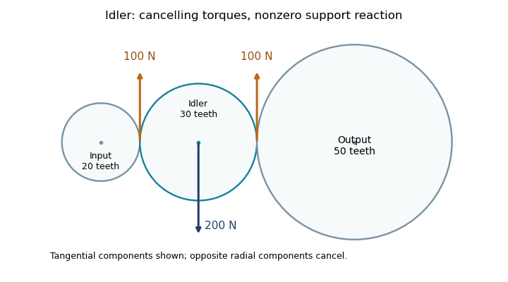
The drawing shows tangential mesh components and their balancing support reaction, rather than physical tooth profiles. Additional shaft loads are outside this ideal balance. The idler therefore affects geometry, forces and potential losses even though its count cancels from the ideal speed ratio.
An idler support reaction is the force exerted by the shaft and bearings that balances the mesh loads and other external loads on an idler gear. A vanishing net transmitted torque does not imply a vanishing resultant force: moments can cancel while forces add. A free-body diagram must retain each tooth-contact force and its point of application. The tangential load in each ideal mesh follows from .[ref]
Elements of Metric Gear Technology by SDP-SI. §7, gear forces; tangential transmitted load and pressure-angle separation of mesh forces
Consider a steady collinear train with input, idler and output reference radii20,30 and50mm. An input torque gives a100N tangential mesh component. On the idler, choose contact positions at and relative to its center, with both tangential forces upward. Their moments are and , but their vector sum is200N upward. For equal20degree pressure angles, the two radial mesh components have magnitude and opposite directions, so they cancel. Neglecting other loads, the net support reaction is200N downward.
This is the combined support resultant, not automatically the load on each bearing. For a hypothetical shaft supported at axial positions and , with the200N upward gear resultant acting at , static equilibrium givesThus and . Idler bearing load sharing depends on placement even when the total reaction is fixed.
Noncollinear shaft layouts rotate the mesh-force directions, and helical gears add gear axial force. Acceleration also changes the balance: the sum of torques must supply the idler's angular acceleration, and unequal mesh loads need not cancel radially. The zero-net-torque example therefore establishes a steady ideal force balance, rather than a universal bearing-load formula.
Idler bearing load sharing determines how an idler support reaction is divided among the shaft's supporting bearing elements. Zero net torque on an ideal steady idler gear does not remove its mesh-induced transverse force. The bearing loads additionally depend on axial positions and the supported-shaft arrangement. Manufacturer guidance separates a radial load between two bearings from an overhung load and treats gear loads as applications of those cases.[ref]
Model the shaft as a simply supported beam with supports A and B at axial coordinates and . Let a gear resultant act upward at , and take upward reactions as positive. Static equilibrium requiressoFor a200N mesh resultant at between supports100mm apart, the downward reactions are120N and80N. Equal division occurs only for the centered load in this symmetric ideal support model.
For overhung idler loading at with the same support span and resultant, and . The farther support's force reverses direction, and the nearer bearing carries more than the applied resultant. This does not violate force balance: . If a particular support cannot provide the required reaction direction, the assumed support model must change.
For loads in two transverse directions, solve each component balance before forming the resultant at each bearing. Helical gears add gear axial force; allocating that thrust requires the actual bearing constraints and cannot be inferred from the transverse lever rule. More than two effective supports generally require deformation compatibility as well as equilibrium. These calculations estimate support forces, rather than directly determining bearing life or internal rolling-element contact loads.
Overhung idler loading occurs when an idler gear's mesh resultant acts outside the axial span of its shaft supports. The overhang creates a lever arm, so the nearer mechanical bearing can carry a larger transverse load than the mesh resultant and the farther support can have the opposite reaction direction. This geometry is separate from whether the idler's two transmitted torques cancel.[ref]
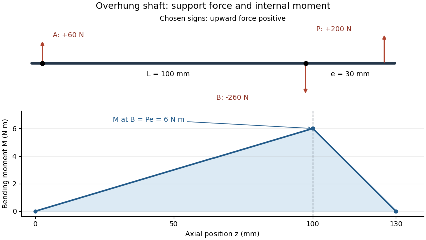
Place ideal radial supports A and B at and . An upward mesh resultant at , with overhang , gives static equilibriumHenceFor , and , A acts upward with60N while B acts downward with260N. Their signed sum balances the applied200N. The larger reaction at B is a lever effect, not an additional external mesh force.
The overhung shaft bending moment immediately next to the near support has magnitude in this ideal model. That bending moment can exist while the net shaft-axis torque on the steady idler is zero. Doubling overhang at fixed load doubles the near-support bending moment and changes the reaction magnitudes to120 and320N.
Idler bearing load sharing must therefore include the gear's axial position, not just its pitch radius and speed ratio. Loads in independent transverse directions can be balanced separately and then combined as vectors. A support model with more constraints requires compatible deformations as well as force balance. Shaft bending and support flexibility can also alter the gear face load distribution, linking the overhang geometry to tooth loading.
An overhung shaft bending moment is the internal bending moment produced when a transverse load acts beyond the shaft's support span. For a single end load at overhang distance , its magnitude immediately next to the nearer support isin the ideal two-support shaft model. The relevant lever arm is the distance beyond that support, rather than the distance between supports. Manufacturer bearing-load guidance distinguishes this arrangement from a load located between bearings.[ref]
Place ideal supports A and B at axial positions and , and apply an upward load at . With upward reactions positive, static equilibrium givesChoosing the internal moment sign consistently with the left-hand force sums, the bending moment along the shaft isIt is continuous at B, reaches there and vanishes at the free end. An ideal bearing need not apply a concentrated couple for the shaft's internal moment at its location to be nonzero: the shaft continues beyond that support.
For original values , and , the reactions are and and the peak moment is . Doubling at fixed doubles that moment. Changing while keeping fixed changes the reactions but leaves unchanged.


For a uniform solid circular shaft in simple elastic bending, overhung shaft bending stress follows from and :At diameter , the example gives about . This excludes stress concentrations and other loads; a shaft's allowable load requires more than this nominal estimate. Bending can remain even when opposing gear torques give zero net shaft-axis torque, because transverse-force moments and axial twisting are different components of the mechanical loading.
Overhung shaft bending stress is the longitudinal normal stress caused by the bending moment from a transverse load beyond the shaft's supports. It differs from twisting due to shaft-axis torque. In the ideal two-support model, the largest overhung shaft bending moment has magnitude , where is the end load and the overhang.[ref]
For a homogeneous linear elastic beam, plane sections in the beam model give longitudinal strain relative to the neutral axis. With Young's modulus ,where is the second moment of area. Thus . For a solid circular shaft of diameter , and the outermost distance is , givingAn original example uses , and . Then and . Reducing diameter to multiplies nominal stress by , raising it to about . The cubic diameter dependence makes a diameter change different from an equal percentage change in overhang.
A measurement check can place opposed axial strain gauges at one shaft station. In a simple axial-plus-bending model, readings and microstrain give axial strain microstrain and bending strain microstrain. This separates two contributions that a single gauge would mix.
The nominal formula excludes local geometric concentrations, multiaxial loading and yielding. It is not a fatigue-life prediction. Under a stationary bending direction, a rotating material point can experience alternating stress, motivating rotating shaft bending fatigue even when the external load is steady. A permissible load requires the actual geometry, material and load history.
Articles by others on the same topic
There are currently no matching articles.