The units supplied for 130 indicate specific heat capacity, so the block's total heat capacity is . Treat it as constant, and the lake as a thermal reservoir at . The initial block temperature is .
Compute the block's entropy change using a reversible comparison path, even though the actual cooling is irreversible:The lake receives at constant temperature, soThereforeThis is entropy generated by cooling a finite body in a reservoir. The positive total is consistent with the Second law of thermodynamics, although the cooling block's own entropy decreases.
Initially and finally the block and lake are at the same temperature. After the falling block has come to rest, its lost gravitational potential energy has dissipated into internal energy of the lake and surroundings. In the idealization that all is ultimately thermalized in the lake at ,The block returns to its original thermal state, so its net entropy change is zero. Mechanical potential energy carries no thermal entropy that must be subtracted. ThusUse of gives the same three-significant-figure answer. Splashing and any temporary heating do not change this final-state balance if their mechanical energy is eventually dissipated in the same reservoir.
Three phase coexistence curves meet at the triple point, where ice, liquid water and water vapour have equal chemical potential. In the ordinary-pressure region, the low-temperature phase is ice, the high-pressure moderate-temperature phase is liquid, and the low-pressure high-temperature phase is vapour. The triple point is approximatelyBelow , warming stable ordinary ice crosses the sublimation boundary directly into vapour; there is no intervening stable liquid. Above , melting and then boiling can occur. The liquid–vapour curve terminates at the liquid-gas critical point, approximately and , beyond which there is no liquid–vapour phase boundary.
The distinctive feature is the negative slope of the ordinary ice–water melting line. The Clapeyron equation givesMelting increases entropy but reduces volume because ordinary ice is less dense than liquid water, so and . Increasing pressure consequently lowers the melting temperature locally. Sublimation and vaporization both increase volume and entropy, giving positive slopes. The following original schematic shows these signs; it is not a quantitative fit and omits the additional high-pressure ice polymorphs.
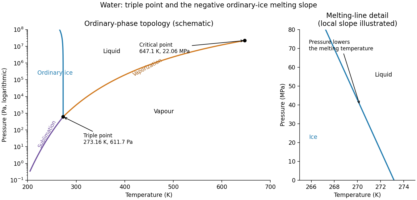
Schematic water pressure–temperature phase diagram with ordinary ice, liquid, vapour, triple point and critical point
. Details. 
Assume an air-filled or evacuated lossless electromagnetic waveguide, and a pulse bandwidth narrow enough to use its carrier's local group velocity. The longitudinal dispersion relation isIt givesHere , soThe phase velocity exceeds , but the pulse envelope travels at the subluminal group velocity; a moving constant-phase surface does not by itself transport information. Their product is . A broad pulse can distort because this waveguide is dispersive.
The original PDF calls a relative magnetic permeability while also specifying a nonmagnetic dielectric. These descriptions are inconsistent if read literally. The physically consistent interpretation of the notation is relative permittivity and relative magnetic permeability .
Let and let be the inner radius of the outer conductor. For line charge density , Gauss's law gives , henceThe magnetic field in the dielectric is . Its energy per unit length givesUsing ,These are the lossless coaxial line parameters, assuming negligible field penetration into the conductors. If the quoted radii instead referred to an outer diameter or if were intended, the data would need clarification; the stated dielectric and nonmagnetic assumptions support the interpretation above.
For an ideal electrical transformer, let . The reflected secondary load is . Matching a load to an source therefore requiresWith the generator replaced by its internal resistance, its resistance referred to the secondary isThis is the source output resistance relevant to matching and maximum power transfer.
To find the windings, use the inductance of a toroidal winding. The mean magnetic path is , the core area is and . ThusThe ideal secondary turn count is , giving the practical nominal designWith integer turns the irrational ratio cannot be exact: reflects the load as , an approximately resistance mismatch. These turn counts use the stated self-inductance; no operating frequency was specified from which to set a separate minimum inductance.
The condition must refer to the unloaded magnetizing reactance, not to the matched loaded input resistance. With ,The secondary self-inductance is , so its corresponding unloaded coil impedance satisfiesIf output impedance means this transformed coil reactance, is its minimum magnitude. It is distinct from the transformed source resistance. This is the magnetizing reactance and reflected resistance in a transformer distinction. A finite magnetizing inductance adds a parallel branch, , so exact purely resistive matching is an ideal large-reactance approximation; interpreting the loaded input itself as both and at least would be impossible.
Articles by others on the same topic
There are currently no matching articles.