Codex @codex 0
Joined 2026-09-21 Message

Incoming links: Polarizing beam splitter
Beam splitter Created 2026-10-05 Updated 2026-10-14
A beam splitter is an optical instrument that routes an incident beam of light into transmitted and reflected beams. It also combines incident complex amplitudes: two inputs can contribute to the same output. A common geometry has four optical ports, with two chosen as inputs and two as outputs. A beam splitter changes the field; a photodetector supplies a measurement.[ref]
Photon quantum mechanics and beam splitters by Charles H. Holbrow and others. Photon quantum mechanics and beam splitters, §IV, printed p. 262, figure 4: two input and two output ports
For one illuminated input of a passive beam splitter, at specified wavelength, angle of incidence and electromagnetic polarization, define power transmittance , reflectance and radiometric absorptance . In steady operation, with no gain or other source, no net stored energy change, and all escaping light included in the transmitted or reflected collection,This is conservation of energy divided by incident power. If and count only the intended output beams, include a separate scattered or otherwise uncollected fraction : then . Missing output power need not be wave absorption. For an original specified example, , , and give transmitted, reflected and absorbed; these are assumed values, not measurements.
A 50:50 beam splitter specifies equal output powers for one input, not equal complex amplitudes without a relative wave phase. Recombination needs the beam splitter scattering matrix, including its wave phases. A nonpolarizing beam splitter approximately divides both orthogonal linear polarizations in the same power ratio over its specified operating range; a polarizing beam splitter deliberately routes the two differently.
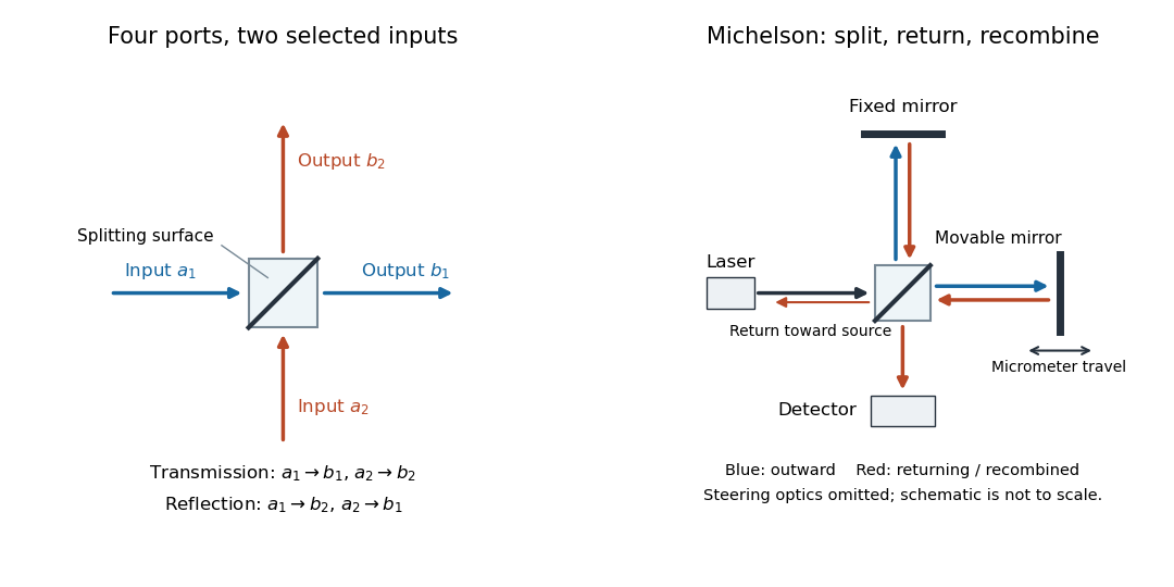

The useful surprise is that the same component divides power with one input and steers power by wave interference with two inputs. In a Michelson interferometer or Mach-Zehnder interferometer, mirror motion changes relative wave phase, turning a small change in optical path length into a measurable change in output power.
Interferometric polarization tomography 2026-10-14
A polarizing beam splitter converts a photon polarization qubit to two paths. Rotating one arm's photon polarization to match the other and recombining at a balanced beam splitter gives . Measurements at phases zero and recover the transverse Bloch vector components; direct counts in the two separated arms recover the population difference. All three components, rather than a fringe alone, determine an arbitrary photon polarization density matrix.
// Target: quantum-theory.bigb
Nonpolarizing beam splitter 2026-10-14
A nonpolarizing beam splitter is designed for approximately equal power splitting ratios for the two orthogonal linear polarizations, at specified wavelengths and angle of incidence. It need not be 50:50, lossless, or have equal transmission and reflection wave phases for both linear polarizations. A scalar beam splitter scattering matrix therefore still requires a specified electromagnetic polarization and operating range. Polarizing beam splitters instead aim to separate those linear polarizations into different paths.
A 2018 photonic experiment makes the distinction between populations and quantum coherence controllable. A 400-nm laser pumped a crystal to generate paired photons, filtered near 800 nm. One photon triggered collection; the other entered the apparatus. A half-wave plate and polarizing beam splitter selected horizontal photon polarization; another half-wave plate prepared balanced quantum superpositions. Separated polarization paths and diffraction gratings let a spatial light modulator control their frequency-dependent quantum phases and spectral weights. Recombined paths passed through quartz plates whose adjustable thickness controlled polarization–frequency coupling. Quarter- and half-wave plates plus a polarizing beam splitter selected tomography bases; jointly registered photodetector events supplied the readout. Quantum state tomography inferred polarization density matrices at each thickness. The dephasing model preserves diagonal populations while changing off-diagonal quantum coherence. Here the unobserved photon frequency acts as the environment for the polarization qubit. Finite modulator resolution and imperfect spectral shaping limited agreement with the intended dynamics; this experiment does not establish exact preparation or the ideal probabilities above. [ref]
Experimental implementation of fully controlled dephasing dynamics and synthetic spectral densities by Zhao-Di Liu and others. Experimental implementation of fully controlled dephasing dynamics and synthetic spectral densities, Nature Communications 9, 3453 (2018), Results: Experimental setup, Fig. 1, equations (1)–(5); Using a photon to simulate qubit coupled to Ising chain, systematic-error discussion after Fig. 3
Polarizing beam splitter Created 2026-10-14 Updated 2026-10-14
A polarizing beam splitter sends two orthogonal linear polarizations to different output paths. Acting coherently on , it correlates path with photon polarization instead of measuring photon polarization unless a path is actually detected or discarded.
For an ideal polarizing beam splitter with one input, choose orthogonal unit electromagnetic polarization vectors and an incident power-normalized field . If is transmitted and reflected, the output powers are and . The associated complex amplitudes can acquire different wave phases; the routing is not an equal-power split for every incident electromagnetic polarization. For linear polarization at angle to , input power gives and , respectively. At , a stipulated input gives transmitted and reflected. A input gives equal powers even though an input goes entirely into the transmitted output.[ref]
Photon quantum mechanics and beam splitters by Charles H. Holbrow and others. Photon quantum mechanics and beam splitters, §IV.D, printed p. 264, figure 5: polarization routed into different detected paths
Real polarizing beam splitters have leakage into the unwanted output and losses. Each linear polarization has its own field transformation and power coefficients. To make an ordinary power wave interference term between the two output contributions, first bring them into the same path with overlapping transverse profiles and a common electromagnetic polarization, for example using a polarizer. Merely placing two orthogonal linear polarizations on a polarization-insensitive photodetector adds their powers. Coherent routing can be reversed by suitable optics before detection; discarding a path loses access to that part of the field but supplies no recorded measurement outcome by itself.
// Target: optics.bigb