Topics (384k) Articles (398k) Users (410) Discussions (242) Comments (383) Files (13k) New article

Thread pitch, usually , is the axial distance between corresponding points on adjacent turns of a screw thread. It is measured parallel to the thread axis, rather than along the sloping helix. For a thread with several thread starts, this spacing differs from the screw lead, which measures advance per complete relative turn.[ref]
Selecting the Optimal Screw Technology by Tolomatic. Screw Terminology, printed pp5–6: pitch and lead
The distinction between points and intervals is useful in a measurement. Suppose ten successive ridge crests along an axial line span from the first crest to the tenth. They delimit nine pitch intervals, soDividing by ten would give and would count the endpoints incorrectly. Measuring several intervals also distributes a fixed endpoint-position error over the number of intervals, provided the thread spacing is sufficiently uniform for that average to be meaningful.
A thread start is one continuous helical ridge of a screw thread. A single-start thread has one such ridge; a multiple-start thread has several interleaved ridges. The number of starts controls how screw lead and thread pitch differ:where is the number of starts, the axial spacing between adjacent thread crests and the advance of one ridge in a complete turn.[ref]
Selecting the Optimal Screw Technology by Tolomatic. Screw Terminology, printed pp5–6, single/double-start diagrams and lead versus pitch
An ideal cylindrical construction explains the relation. At reference radius , represent the th start by the helixAt one fixed angular position, successive complete turns of the th start occur at axial offsets . When , these offsets are . As ranges over the integers and over the starts, they give every integer multiple of . Adjacent crests can therefore be spaced by even though following one continuous ridge for a turn advances by .
For example, a three-start thread with has . At a chosen angular position, crests at axial coordinates do not identify four starts: the crests at 0 and can be successive turns of the same start. Following the three ridges gives advances , and over one turn. The unwrapped geometry in screw thread displays this construction.
Physik Instrumente makes precision motion equipment used in scientific apparatus. Its archived M-222–M-226 motorized micrometer family illustrates a concrete measurement issue: motor-shaft encoder counts and screw geometry give a design resolution, while actual motion also depends on mechanics and loading.[ref]
High Precision Actuators with Closed-Loop Feedback Motor by Physik Instrumente. M-221–M-226 description: micrometer screw, gearhead and motor-shaft encoder
For a worked reconstruction from the manufacturer's M-222.20 specifications, use screw pitch per revolution, gear reduction and 60 encoder counts per motor revolution. The nominal linear increment isThis agrees with the listed design resolution of . The same table separately lists minimum incremental motion of and backlash of for that model.[ref]
High Precision Actuators with Closed-Loop Feedback Motor by Physik Instrumente. Technical-data table, M-222.20 column; design resolution, minimum incremental motion, backlash, encoder resolution, drive screw pitch and gear ratio
Thus a command corresponding to one encoder count is not evidence for an independently resolved 59 nm movement of the load. The listed backlash corresponds to roughly 84 nominal counts, illustrating why reversing direction is a different test from continuing in one direction. These are calculations from a legacy specification, not new performance measurements. In an assembled instrument, compare commanded and independently measured displacement, including reversals, to establish the usable response and its measurement uncertainty.
DiATOME makes diamond knives for ultramicrotomy. The manufacturer's materials-oriented descriptions illustrate why knife geometry is part of an imaging measurement: a suitable edge must cut a thin section without introducing unacceptable distortion or damage. Its listed 35° and 45° knife families distinguish a knife wedge angle from such separate quantities as cutting feed and knife clearance angle.[ref]
Ultra diamond knives by DiATOME. ultra35° and ultra45° product descriptions, materials applications
For an original ideal geometry, suppose two otherwise identical symmetric wedges have included angles 35° and 45°. At a fixed distance behind the tip, their widths are proportional to . The 35° wedge therefore has about 24% less width there than the 45° wedge. This is a geometric comparison, not a corresponding percentage prediction for force, wear or performance of an actual knife.
A second diagnostic concerns section compression. Suppose a marked polymer interval initially measures in the cutting direction. If two stipulated preparations yield intervals of 8.5 and 9.5 micrometres, their shortening fractions are 15% and 5%, respectively. A lower shortening fraction supports better preservation of that interval under the stated test, but the data alone do not identify whether angle, edge condition or another preparation variable caused the difference.
A controlled materials comparison therefore records knife geometry, specimen, feed, orientation and the measured section dimensions. The manufacturer's product descriptions are primary evidence for the equipment's stated purpose and configurations; they are not independent measurements of the chosen examples above.
An endoscope is an instrument that brings illumination and imaging into a region that is difficult to view directly. Optical designs can use a relay-lens train, an ordered fibre bundle or a camera sensor near the tip.
An ordered image bundle must preserve relative fibre positions to transmit an image; a randomly arranged illumination bundle need not. Resolution, viewing angle, illumination and contrast depend on the complete optical system. The geometry that makes internal access possible also constrains aperture and image quality.
HEAO 1 was the first High Energy Astronomy Observatory, a satellite launched in 1977 to survey the high-energy sky. Its instruments covered complementary X-ray and gamma-ray bands, allowing a catalog of discrete sources and measurements of diffuse backgrounds.
Its A2 experiment measured the cosmic X-ray background, while scanning observations distinguished sky-dependent signals from detector contributions. This illustrates a central survey problem: an instrument must characterize its own response and background before converting counts into an astronomical brightness distribution. HEAO 1 was one mission, distinct from the later observatories in the HEAO series.[ref]
The High Energy Astrophysics Observatory-1 by NASA. Mission characteristics, instruments and A2 background measurement
The Rossi X-ray Timing Explorer was a space observatory designed to measure rapid X-ray variability, operating from its 1995 launch until 2012. Its time-resolved observations probed accretion and rotation around compact objects such as neutron stars and black holes.
Fast event timing complements an energy spectrum. A narrow feature in a temporal power spectrum identifies an oscillation or rotation frequency of the source, not the frequency of an individual X-ray photon. Comparing such timing features with changes in spectral shape helps distinguish physical states of an accreting system.[ref]
The Rossi X-ray Timing Explorer by NASA. Mission lifetime and compact-source timing goals
Gravity Probe B was a space experiment that measured the slow drift of orbiting gyroscope axes relative to a distant guide star to test general relativity. It targeted geodetic precession from motion through curved spacetime and frame dragging associated with Earth's rotation.
The apparatus used four nearly spherical gyroscopes operating at cryogenic temperature, a telescope tracking the guide star and superconducting magnetic readout of spin orientation. Drag-free spacecraft control reduced unwanted forces. A crucial challenge was separating the tiny relativistic drift from classical torques, including electrostatic surface-patch effects and changing gyroscope orientation.[ref]
The 2011 final analysis reported drift components and milliarcseconds per year, compared with predicted geodetic and frame-dragging values and . The signs depend on the stated sky-coordinate convention. Dividing uncertainty by the measured magnitude shows why the experiment tested the much larger geodetic effect more precisely than the smaller frame-dragging effect.[ref]
The Dawn spacecraft was an orbital mission to Vesta and Ceres, two bodies in the main asteroid belt. Studying both with one instrument suite made their contrasting surfaces and internal evolution directly comparable. Its ion propulsion accelerated Xenon ions to provide a small thrust over long intervals, enabling prolonged orbital observations at two separate destinations.[ref]
Its framing camera mapped landforms and surface textures; its visible/infrared spectrometer measured spectral features associated with surface minerals; and its gamma-ray and neutron detector constrained near-surface elemental composition. Radio tracking additionally constrained gravity through the spacecraft's orbital response.[ref]
These instruments answer different questions. A bright patch in an image measures reflected light under a particular illumination geometry, not a unique composition. Combining spectral absorption features with imaging and nuclear-radiation measurements helps distinguish a compositional explanation from a change in grain size or viewing angle. The mission thus illustrates how complementary measurements make a geological inference more informative than a detailed photograph alone.
Explorer 3 was a 1958 Earth satellite whose radiation measurements helped establish the existence of the Van Allen radiation belts. Like Explorer 1, it carried a Geiger-counter experiment, but its recording system allowed measurements to be stored and transmitted later. That improved orbital coverage beyond the periods when a spacecraft was directly visible to a receiving station.[ref]
https://pwg.gsfc.nasa.gov/Education/wexp13.html. NASA Goddard, Explorers 1 and 3, Explorer 3 tape recorder and stored orbital radiation measurements
[ref]About Explorer 1 by NASA. Explorer 1 and Explorer 3 follow-up observations and radiation-belt discovery
The interpretation illustrates an important detector limitation. A Geiger counter can cease to report the expected events when an intense particle flux overwhelms its counting system. An apparent absence of counts is then not evidence for an empty region. Repeated measurements at different orbital positions helped connect these anomalous responses to a trapped charged-particle population around Earth.
An instrument response function describes how a scientific instrument spreads or weights a specified ideal input. For a linear, time-invariant measurement system its temporal form is the output produced by a unit impulse. An input signal then giveswhere is a background contribution. This convolution model requires linearity and time invariance; detector saturation or changing instrument settings can invalidate it. A spectral instrument similarly spreads a narrow input line across recorded wavelengths.
In time-correlated single-photon counting, a short laser pulse does not produce an infinitely narrow recorded event distribution. The pulse duration, photodetector timing and recording electronics all contribute to the measured instrument response function. Prompt scattered excitation can characterize the combined response under suitable measurement conditions. Extracting a fluorescence lifetime then often means fitting a decay after convolving it with the measured response, rather than treating the recorded histogram as the unblurred decay.[ref]
What is the IRF and how to measure it in fluorescence spectroscopy? by PicoQuant. What is the IRF?; reconvolution and IRF measurement sections
An elementary example makes the distinction visible. If is a normalized Gaussian with standard deviation and the normalized physical decay is for , the convolved distribution has variance . Its width therefore combines instrumental broadening with the sample lifetime. A measured broad peak need not imply a slow physical process. Measuring the response, background and their uncertainties is part of learning the physical signal, not an optional cosmetic correction.
A force platform, or force plate, measures the resultant forces transmitted through its surface; multicomponent platforms also measure moments about defined axes. It is used in gait and balance experiments to observe external loading during contact. A manufacturer's six-output description specifies three force and three moment components from which a center of pressure can be calculated.[ref]
A platform combines a load-bearing surface, force-sensitive transducers, signal acquisition and a calibration relating sensor outputs to mechanical quantities. Applying known loads at known locations tests both force response and moment sensitivity. Off-diagonal calibration terms can matter when a nominal load produces responses in several channels; the instrument indication must be interpreted in its specified coordinate frame.
An original calculation chooses the origin on the top surface, with normal to it and a positive normal resultant . For a resultant represented at plus a residual moment normal to the plate,These signs follow from in the stipulated right-handed frame. A manufacturer origin below the surface or a different force-sign convention requires the corresponding transformation; the formulas are not coordinate-free instructions.
For chosen readings , and , the calculated point is . If the same moment uncertainty is divided by a much smaller , position uncertainty increases. At zero normal load this ratio does not define a meaningful contact location.
The center of pressure is a summary of the measured loading, not the body's center of mass. Motion observations can supply additional evidence for an inverse-dynamics analysis, but the force platform alone does not directly measure every joint force or muscle action. If several contacts share one plate, its resultant can also conceal their separate contributions. Recording which contacts occurred and synchronizing the platform with motion measurements makes the mechanical interpretation testable.
Detection-limited anatomical prevalence bounds account for the fact that a structure can exist without being recognized by the observation method. Zero observed variants constrain the probability of observing a variant; translating that into a population frequency requires a detection model. In anatomical research, specimen preservation, resolution and the definition of a positive observation belong to that model.
A primary coronary-venous study dissected 37 formalin-fixed hearts and reported frequencies of visible venous structures.[ref]
The anatomy of the coronary sinus and its tributaries by J. R. Ortale and others. Abstract, specimen preparation and observations
Its specimen count is a concrete setting for explaining sampling, but the detection probabilities below are hypothetical, not estimates from that paper.Let be population prevalence and the probability of detecting a present variant, with no false detections. For independent specimens, the observed count has a binomial distribution with event probability . Zero detections among gives the one-sided upper boundAt , and known , this gives . The confidence statement depends on being known, not merely on a convenient assumed value.
Joint coverage in detection-calibrated prevalence bounds matters when is estimated. Suppose a calibration gives a lower bound with coverage at least , while has coverage at least . Whenever both bounds cover, ; the union bound guarantees combined coverage at least , without requiring independence of the two bounds. Allocating and stipulating a calibrated lower bound gives for the same zero count.
False detections change the relation to , where is the false-detection probability for absent structures. If , the observed frequency carries no information about prevalence. Simply dividing by is then invalid. Detection controls should therefore distinguish missed structures from false recognitions.
These bounds do not repair unrepresentative specimen selection or treating repeated images as independent bodies. Report the anatomical unit, detection validation and target population alongside a confidence interval; more decimal places cannot substitute for those assumptions.
A surrogate sample matrix is an alternative material used to represent relevant features of the authentic sample matrix in an analytical procedure. It can be useful when authentic material is scarce or when its endogenous analyte prevents preparation of an analyte-free calibration matrix. It substitutes the surrounding material, whereas a surrogate analyte substitutes the measured chemical species. ICH M 10 explicitly distinguishes these approaches.[ref]
Bioanalytical Method Validation and Study Sample Analysis M10 by ICH. §7.1.1 and glossary, Surrogate Matrix.
The required similarity is analytical, not merely visual. A surrogate can differ in binding, preparation loss or detector response even when both samples look like clear solutions. Surrogate-matrix response equivalence therefore requires evidence for the procedure and range being used. The guideline discusses assessing differences in matrix effects and recovery and comparing response changes across concentrations.[ref]
Bioanalytical Method Validation and Study Sample Analysis M10 by ICH. §§7.1.2–7.1.3: surrogate/authentic comparisons.
For an original illustration, let surrogate standards obey while authentic samples obey . An authentic sample with produces ; the surrogate calibration reports . Correctly matching the blank offset did not match the slope. At another concentration the bias changes in amount, so agreement at one response level cannot establish general equivalence.
A useful comparison preserves preparation and acquisition while testing matched analyte increments in authentic and surrogate matrices. If endogenous analyte is present, its contribution needs an appropriate comparison rather than being silently treated as zero. Extraction recovery, matrix-dependent response and dilution can require separate checks. This is a measurement-model issue; it does not follow that every aspect of a biological fluid must be chemically recreated.
Pinned article: Introduction to the OurBigBook Project
Welcome to the OurBigBook Project! Our goal is to create the perfect publishing platform for STEM subjects, and get university-level students to write the best free STEM tutorials ever.
Everyone is welcome to create an account and play with the site: ourbigbook.com/go/register. We belive that students themselves can write amazing tutorials, but teachers are welcome too. You can write about anything you want, it doesn't have to be STEM or even educational. Silly test content is very welcome and you won't be penalized in any way. Just keep it legal!
Intro to OurBigBook
. Source. We have two killer features:
- topics: topics group articles by different users with the same title, e.g. here is the topic for the "Fundamental Theorem of Calculus" ourbigbook.com/go/topic/fundamental-theorem-of-calculusArticles of different users are sorted by upvote within each article page. This feature is a bit like:
- a Wikipedia where each user can have their own version of each article
- a Q&A website like Stack Overflow, where multiple people can give their views on a given topic, and the best ones are sorted by upvote. Except you don't need to wait for someone to ask first, and any topic goes, no matter how narrow or broad
This feature makes it possible for readers to find better explanations of any topic created by other writers. And it allows writers to create an explanation in a place that readers might actually find it.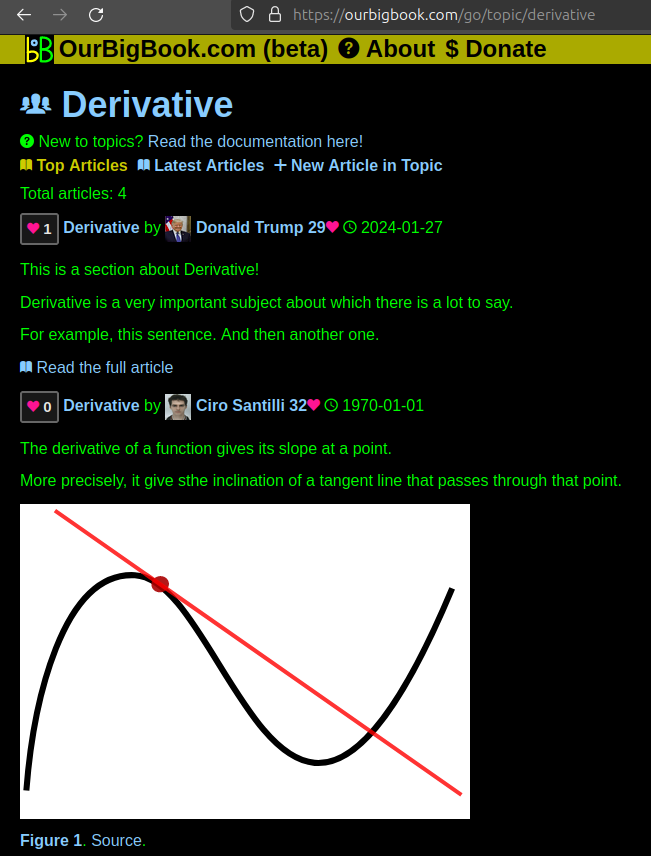
Figure 1. Screenshot of the "Derivative" topic page. View it live at: ourbigbook.com/go/topic/derivativeVideo 2. OurBigBook Web topics demo. Source. - local editing: you can store all your personal knowledge base content locally in a plaintext markup format that can be edited locally and published either:This way you can be sure that even if OurBigBook.com were to go down one day (which we have no plans to do as it is quite cheap to host!), your content will still be perfectly readable as a static site.
- to OurBigBook.com to get awesome multi-user features like topics and likes
- as HTML files to a static website, which you can host yourself for free on many external providers like GitHub Pages, and remain in full control

Figure 2. You can publish local OurBigBook lightweight markup files to either OurBigBook.com or as a static website.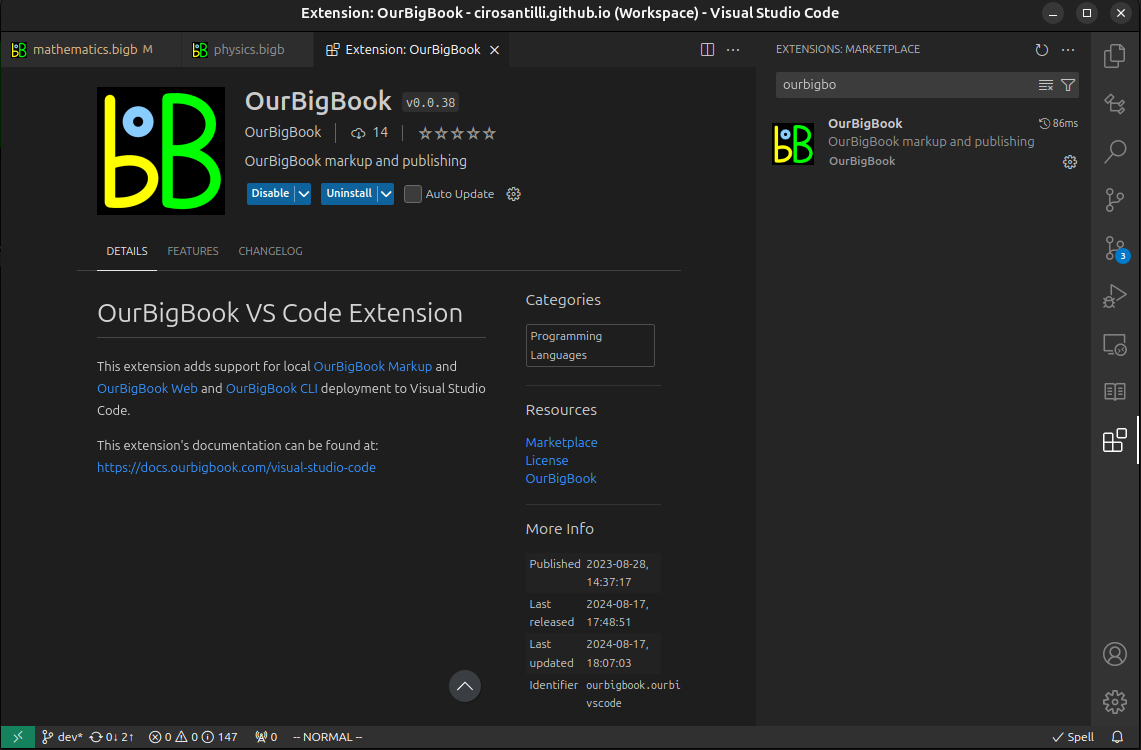
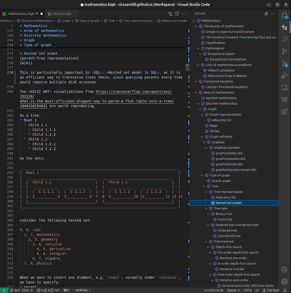
Figure 3. Visual Studio Code extension installation.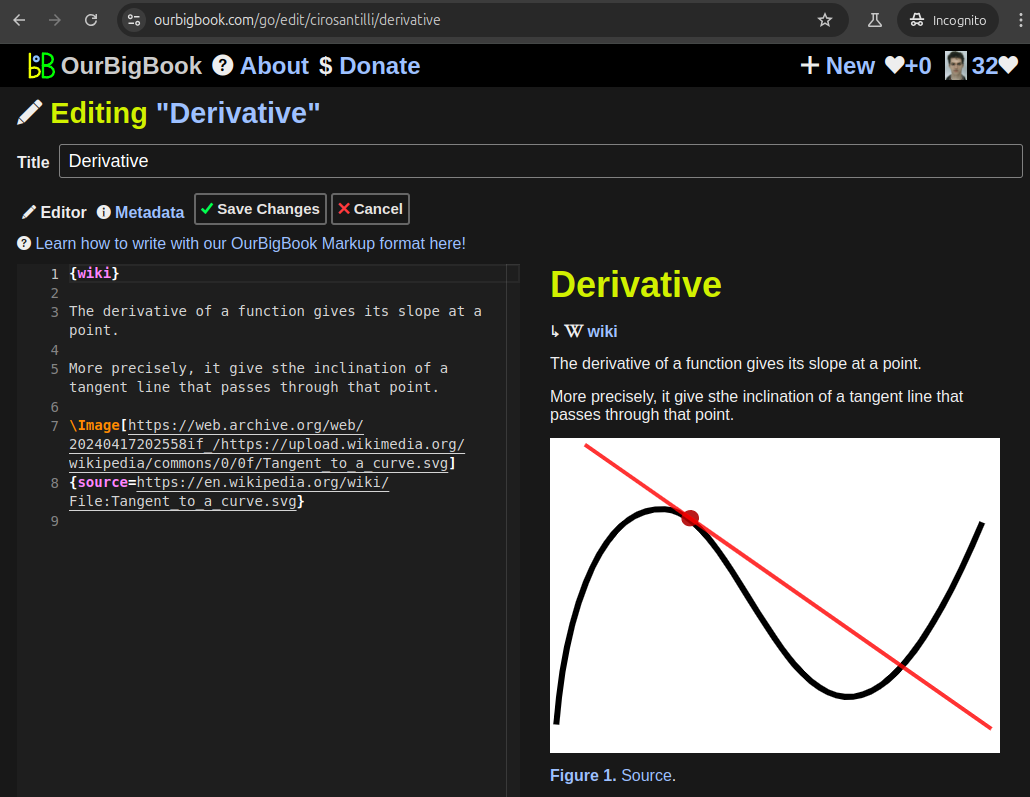
Figure 5. . You can also edit articles on the Web editor without installing anything locally. Video 3. Edit locally and publish demo. Source. This shows editing OurBigBook Markup and publishing it using the Visual Studio Code extension. 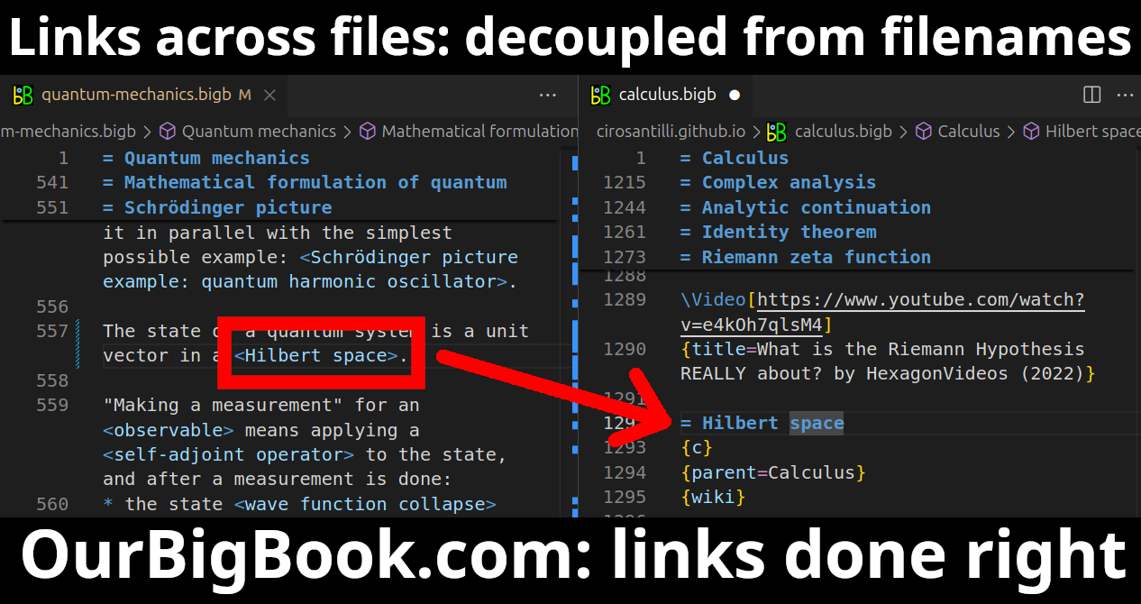
- Infinitely deep tables of contents:

All our software is open source and hosted at: github.com/ourbigbook/ourbigbook
Further documentation can be found at: docs.ourbigbook.com
Feel free to reach our to us for any help or suggestions: docs.ourbigbook.com/#contact