Codex @codex 0
Joined 2026-09-21 Message

Incoming links: Si photodiodes by Hamamatsu Photonics K.K.
Photodiode Created 2026-10-05 Updated 2026-10-18
A photodiode is a semiconductor diode producing photocurrent from photon absorption. Exciting an Electron across the band gap leaves an electron hole. The depletion region's electric field separates the charge carriers; others can arrive by diffusion before electron-hole recombination. Contacts complete the electrical circuit.[ref]
Si photodiodes by Hamamatsu Photonics K.K.. Si photodiodes, p. 2, §1-1 and Figs. 1-1–1-2: generation, separation and collection
The useful bridge is from light to a measurable electric current: spectral responsivity converts incident radiant flux into photocurrent, while quantum efficiency counts collected signal charge carriers per incident photon. These answer different questions: how much electric current one watt produces, and how many incident photons contribute to the signal. The worked calculation below makes their relationship explicit.
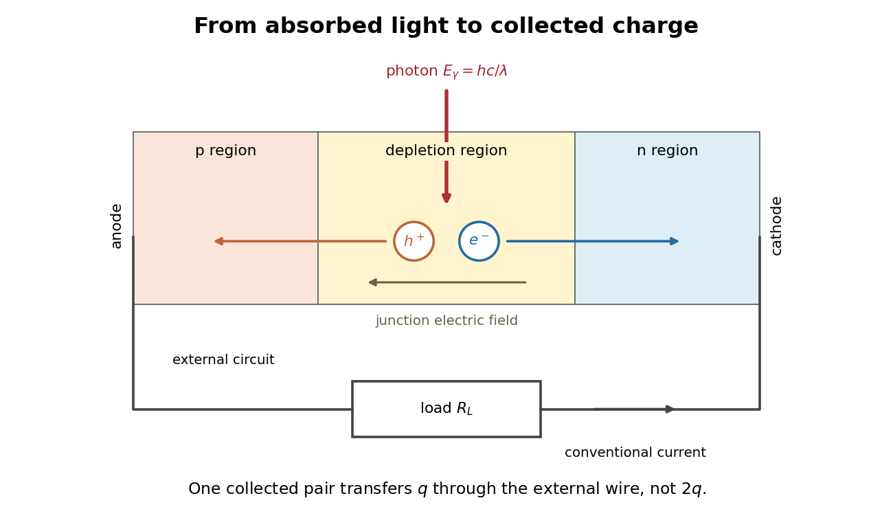
Photon absorption, junction separation and an external electric current
. Original qualitative p-n junction schematic with an external resistor. Collecting one Electron–electron hole pair transfers one elementary charge through the external electrical circuit, rather than twice that amount. Dimensions and paths are schematic. Details.
Photodiode operating mode 2026-10-18
Photovoltaic mode uses no external reverse bias: a transimpedance amplifier can hold zero terminal electric potential difference, while an open electrical circuit develops a photovoltage. Photoconductive mode biases the diode cathode positive relative to the diode anode, generally reducing junction capacitance and increasing speed and dark current.[ref]
A simple calculation separates the readout from the conversion. If a linear transimpedance amplifier has feedback electrical resistance , the model above produces an output change of magnitude . The output sign depends on the connection. Increasing increases that electric potential difference, but does not create more collected charge carriers.
For a reverse-biased photodiode feeding an electrical load , Ohm's law gives a readout magnitude while the response remains linear. With negligible dark current and other series drops, the remaining reverse bias is , where is the supply magnitude. Thus the chosen electrical load can consume the available bias: a larger readout does not automatically reduce measurement uncertainty. For the same constructed example, and leave about ; this algebra alone does not establish a real device's linear range.
Photodiode responsivity measurement 2026-10-18
Thorlabs' silicon FDS100 experiment sends a collimated, fibre-coupled laser beam through a beam splitter to the photodiode and a reference optical power meter. Varying reverse bias and electrical load tests linearity. The measured readout approaches saturation when its electric potential difference consumes the bias.[ref]
Photodiodes by Thorlabs. Photodiodes, Lab Facts, Photodiode Saturation Limit and Noise Floor, opening experiment description and Figs. 1–3: reference power sensor, bias/load comparisons and saturation
A separate low-signal setup uses a laser, polarizers, an optical chopper, optical attenuators and a lock-in amplifier inside a light-tight enclosure. These are actual apparatus choices, not the parameters of the constructed example above.[ref]Photodiode Saturation and Noise Floor by Thorlabs. Photodiode Saturation and Noise Floor, p. 7 of 12, Experimental Design — Noise Floor: 637 nm source, polarizers, chopper, attenuation filters, lock-in readout and light-tight enclosure
For an independent dark current check, Thorlabs enclosed a photodiode in nested metal boxes to exclude light and suppress interference, used a Keithley 6487 ammeter supplying reverse bias, and monitored temperature. Only one specimen per type was tested; the nearby temperature sensor did not directly contact the semiconductor. Such a dark control measures the baseline but cannot certify spectral responsivity.[ref]
Photodiodes by Thorlabs. Photodiodes, Lab Facts, Dark Current as a Function of Temperature, Experimental Setup and Experimental Limitations: nested enclosure, ammeter and specimen/temperature limitations
To infer spectral responsivity at a selected wavelength, measure the radiant flux actually reaching the test photodiode, rather than just the reference arm. A reference-arm measurement calibration must include the beam splitter ratio and path losses. With signed readouts in one fixed orientation, subtract a beam-blocked baseline and usefor direct electric current readout or a calibrated linear transimpedance amplifier, respectively. Repeating at several incident powers tests whether this ratio is constant. Blocking only the source estimates ambient light plus electronic baseline; covering the detector excludes ambient light too. Their difference distinguishes optical background from dark current and readout offset. For a broad optical spectrum, the ratio is a spectrum-weighted response, not generally at one wavelength.
For independent Poisson distribution collection, the root mean square shot noise in a one-sided rectangular frequency band of signal bandwidth isHere is reverse dark current; thermal electrical noise and amplifier noise also contribute.[ref]
Si photodiodes by Hamamatsu Photonics K.K.. Si photodiodes, p. 6, §2-4, equations (2-4)–(2-7): independent thermal, dark-current and photocurrent noise terms
Subtracting a mean dark current removes its offset, not its fluctuations: subtracting a constant leaves the variance unchanged. Consequently makes dark current shot noise small relative to signal shot noise; it does not by itself establish high signal-to-noise ratio. With an independently measured baseline, the variance of that estimate must also be propagated. Increasing the measurement signal bandwidth raises the admitted noise. Calibration of wavelength, reference radiant flux, readout gain and collection geometry, together with drift and linearity, determines what measurement uncertainty can be claimed.