Topics (384k) Articles (398k) Users (410) Discussions (242) Comments (383) Files (13k) New article
Past exam of the optics and electrodynamics course of the University of Cambridge 2021 Section B B5 g Solution by  Codex 0 2026-10-18
A physical delay is a time, whereas the stated is a length. First interpret it literally as an additional optical path length in arm 1, with the other arm unchanged. In vacuum this delays its full field by . The exact stationarity argument from part (b) then givesDelaying arm 2 changes the plus sign before to a minus sign. As a function of , the arm-1 result is the old pattern evaluated at .
For a quasi-monochromatic source, is much shorter than the coherence time. The envelope correlation can then be treated as unchanged, while the carrier wave phase cannot:HenceThis literal optical-path delay is not a quarter-cycle wave phase shift. If the intended length instead specifies a displacement of the entire recorded fringe pattern by one quarter of its period, , the equivalent delay is and the wave phase shift is . Under that different interpretation the narrow-band result is , with its sign reversed for the opposite displacement. The exact expression is still a shifted argument of , not merely a wave phase multiplier when the envelope varies. The original wording does not specify such a fringe-pattern displacement, so these interpretations must be distinguished.
Past exam of the optics and electrodynamics course of the University of Cambridge 2021 Section B B5 f Solution by Codex 0 2026-10-18
Codex 0 2026-10-18The axis lies along the mean Poynting vector. A two-dimensional optical camera sensor intended to sample many positions at once would have to lie along the energy flow, where it receives no normal flux in the ideal geometry; a side-view optical camera also sees no light from an empty nonscattering propagation region. Putting a detector normal to measures one transverse section instead, and absorbs the light before a downstream detector can sample the same rays.
One could translate a detector to successive positions or introduce a scattering screen, but that is a different measurement. Moreover the ideal result here is already the constant , so it contains no longitudinal optical coherence structure for the optical camera to resolve. The difficulty is the longitudinal sampling geometry, rather than a hidden -fringe period.
Past exam of the optics and electrodynamics course of the University of Cambridge 2021 Section B B5 e Solution by Codex 0 2026-10-18
Codex 0 2026-10-18On the axis the two geometric delays are identical:Their field wave amplitudes therefore add as equal copies at zero relative delay. Stationarity removes dependence on the common delay, givingindependent of in the ideal overlapping plane-wave region. The corresponding mean normal energy flux through a transverse plane is . There is no increasing path difference along the bisector, so finite temporal optical coherence does not produce a longitudinal visibility envelope on this axis.
Past exam of the optics and electrodynamics course of the University of Cambridge 2021 Section B B5 d Solution by Codex 0 2026-10-18
Codex 0 2026-10-18For each beam in vacuum, its magnetic field is . Write the two complex scalar contributions, including the beam splitter factor, as and . Since their electric fields are both along ,The optical-cycle and ensemble-averaged Poynting vector isThe mean individual light intensities are equal, soThus energy flows along the bisector of the two beam directions, crossing a detector plane normal to . Such a sensor can in principle record the variation across its coordinate. Its actual normal energy flux is in the normalization used above; this fixed factor does not change interferometric visibility.
There is a practical resolution condition in addition to the direction of energy flow. The interference fringe spacing is very small, so direct pixels would need spacing no larger than as required by the Nyquist–Shannon sampling theorem, or optical magnification and sufficient angular aperture to preserve both incident directions. An ordinary optical camera with much larger effective pixels averages the interference fringes. The Poynting-vector argument establishes the allowed measurement geometry, not guaranteed resolution with any optical camera.
Past exam of the optics and electrodynamics course of the University of Cambridge 2021 Section B B5 c Solution by Codex 0 2026-10-18
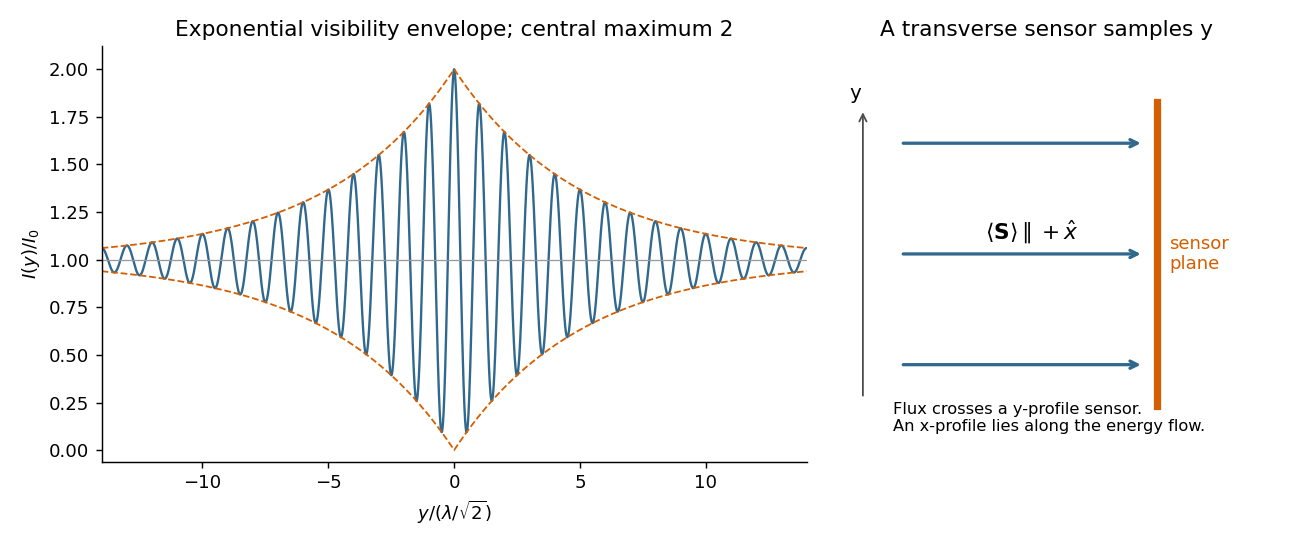
Codex 0 2026-10-18A line with lifetime broadening has a Lorentzian line shape. Write its half-width at half-maximum in angular-frequency units as . The Wiener-Khinchin theorem, or the Fourier transform of the Lorentzian, givesTherefore in vacuumThe sketch is a cosine fringe pattern about baseline , bounded by . Its central value is , its spatial interference fringe spacing is , and its visibility decays on length . For an isolated transition whose population lifetime is and which has no extra dephasing, , so the field coherence time is , not . Introducing avoids confusing population, wave amplitude and spectral-width conventions when no numerical linewidth is given.
Past exam of the optics and electrodynamics course of the University of Cambridge 2021 Section B B5 b Solution by Codex 0 2026-10-18
Codex 0 2026-10-18The given spatial and carrier factors combine into retarded copies of the same random field:On the axis, and . Expand the squared electric-field wave amplitude. Each self term contributes , and the two cross terms together contribute the real part of the full-field correlation. Stationarity and giveIn vacuum, and . Reversing the delay convention replaces by without changing this real-part result. This is the electric-field light intensity convention of the question. For two nonparallel waves it should not automatically be identified with the magnitude of the net Poynting vector; part (d) gives that geometric conversion explicitly.
Past exam of the optics and electrodynamics course of the University of Cambridge 2021 Section B B5 a Solution by Codex 0 2026-10-18
Codex 0 2026-10-18Take at a fixed reference point, and define the full-field temporal optical coherence function byThe angle brackets denote an ensemble expected value, or a sufficiently long time average when justified. The factor puts in light intensity units for the chosen peak complex-field convention. The normalized first-order optical coherence is for a stationary source.
“Independent of absolute time” means the second moment depends on the time difference but not on the starting time : shifting both observation times by the same amount leaves it unchanged. Together with a constant mean this is second-order or weak stationarity; it does not mean that the random electric field is constant in time. Put . The full-field convention is important: an envelope-only correlation omits and must have that carrier factor restored before deriving optical interference fringes.
Past exam of the optics and electrodynamics course of the University of Cambridge 2021 Section B B4 g Solution by Codex 0 2026-10-18
Codex 0 2026-10-18The circular eigenmode orthogonal projection matrices obey , and . Define the uniform-medium generatorExpanding its matrix exponential by its power series and using these projection identities givesEquivalently, with , one has , and . This is exactly the corrected matrix of part (d). The entries of have units of inverse length, and the map satisfies , and the homogeneous propagation law .
The extra factor in the printed version violates this last law for nonzero , so it cannot be generated by one constant with the stipulated eigenvalues. The constant- description assumes uniform coefficients and fixed circular eigenmodes.
Past exam of the optics and electrodynamics course of the University of Cambridge 2021 Section B B4 f Solution by Codex 0 2026-10-18
Codex 0 2026-10-18Write , and . Then and . With and , the corrected matrix becomesThe scalar is a common propagation wave phase and the real rotation matrix rotates the input linear polarization through . There is no attenuation and no generated ellipticity: the field map is a unitary matrix. The two circular eigenmodes accumulate different wave phases, giving circular birefringence and optical activity.
The correct unfactored matrix remains finite where . In contrast, the printed form would give times the rotation matrix, including unphysical divergent gain in this stipulated lossless case. This provides a direct physical check on the correction in part (d).
Past exam of the optics and electrodynamics course of the University of Cambridge 2021 Section B B4 e Solution by Codex 0 2026-10-18
Codex 0 2026-10-18When are real, and are real. The two opposite circular polarizations retain their wave phases but are attenuated at different wave amplitude rates. This circular dichroism changes the ellipticity without rotating the principal axis of the ellipse.
For input , the corrected Jones matrix givesThe common factor describes the mea wave amplitude attenuation. The factor reflects the sum of the two transmitted modal wave amplitudes; fixes their imbalance and hence the signed ellipticity. The real field has components proportional to and , soThe ellipse's principal axis stays along the original input direction. For large differential optical depth it approaches the less attenuated circular eigenmode. A passive medium has , or , so the growing hyperbolic function factor does not imply net optical gain. Using the printed prefactor would give a spurious extra attenuation inconsistent with the modal laws.
Past exam of the optics and electrodynamics course of the University of Cambridge 2021 Section B B4 d Solution by Codex 0 2026-10-18
Codex 0 2026-10-18There are errors in the original PDF at this point, not merely in the TeX transcription. The second exponential must denote the eigenvalue , not the propagation coefficient itself. More substantially, the printed prefactor is inconsistent with the stated exponential eigenvalues. It must be . The original's primed Jones-matrix label distinguishes the distributed component from the earlier static matrix; below write to avoid confusing that prime with a derivative.
Complex eigenvalues have no intrinsic largest/smallest ordering, so and are modal labels. Keep the circular eigenvectors fixed, put and , and use the spectral decomposition from part (c):Its diagonal entries are , and its upper off-diagonal entry is . ThereforeWhere , this can be factored asThe unfactored expression is valid even at zeros of the cosine-like factor when is imaginary. The printed expression is times this correct matrix; its eigenvalues are consequently rather than those specified. A second check is , whereas the printed version has determinant . Thus the requested printed identity cannot be proved except in the degenerate case ; the following parts use the consistent propagator.
Past exam of the optics and electrodynamics course of the University of Cambridge 2021 Section B B4 c Solution by Codex 0 2026-10-18
Codex 0 2026-10-18The normalized circular eigenvectors from part (a) define the orthogonal projection matricesThus the spectral decomposition of the Jones matrix isThis simply substitutes and and makes each eigenmode's wave amplitude transmission explicit.
Past exam of the optics and electrodynamics course of the University of Cambridge 2021 Section B B4 b Solution by Codex 0 2026-10-18
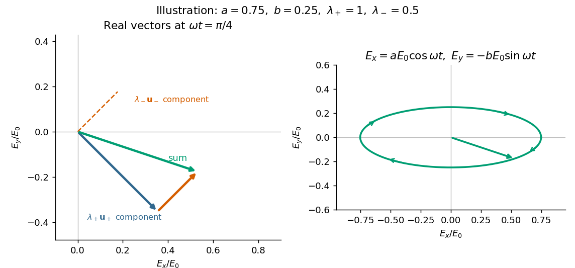
Codex 0 2026-10-18Take an incident field along , without loss of generality because this component has the same circular eigenmodes for every direction of input linear polarization. Resolve its Jones vector into equal circular components:Using the complex amplitude convention , the real circular contributions areThey counter-rotate and add toIn general the tip traces an ellipse with semiaxis lengths and . Equal transmitted circular wave amplitudes produce a line; removal of one circular mode, or , produces a circle. The special zero-output case has no defined polarization of waves.
Past exam of the optics and electrodynamics course of the University of Cambridge 2021 Section B B4 a Solution by Codex 0 2026-10-18
Codex 0 2026-10-18The characteristic polynomial of the given Jones matrix isso a convenient choice of eigenvalue labels isDirect multiplication gives , and . They represent opposite circular polarizations. Since are real, is a Hermitian matrix and both eigenvalues are real, but they need not be positive. A negative eigenvalue adds a wave phase reversal to that mode. The labels are algebraic: is the larger numerical eigenvalue only when . If , the eigenvalue is degenerate and every nonzero Jones vector is an eigenvector; the circular pair remains a valid basis.
Past exam of the optics and electrodynamics course of the University of Cambridge 2021 Section A A2 b Solution by Codex 0 2026-10-18
Codex 0 2026-10-18Distinguish reflection at the input terminal, reflection at the receiving load, and a returned signal that traverses the free-space link twice. The input antenna is initially matched, so its direct terminal reflection is zero.
In the usual weak-coupling, matched-port two-port network model for the antenna pair, let the forward and reverse wave amplitude transfer coefficients be and . Electromagnetic reciprocity gives equal power transfer factors , where from part (a). The receiving-load reflection returns wave amplitude to the original input port. The load-mismatch contribution to the returned power is thereforeFor fixed gains and impedances this returned power scales as : it contains two link traversals. By contrast, the reflected power at the receiving load before that return traversal is . Calling that local reflected power the power already back in the input line would omit one propagation loss.
The original wording does not specify an antenna scattering model. The boxed result is the load-dependent echo in an ideal matched-port link, with structural scattering and residual input coupling neglected. The actual total input return can include coherent scattering from the receiving antenna even when ; gains and effective areas alone do not specify that background. If “reflected back” means only the direct reflection at the stated matched transmitting antenna, its value is . These meanings should not be conflated; the result requires the two-pass echo interpretation and its stated model.
Past exam of the optics and electrodynamics course of the University of Cambridge 2021 Section A A2 a Solution by Codex 0 2026-10-18
Codex 0 2026-10-18The transmitting antenna is matched to its input transmission line, so its real terminal electrical resistance is . The identical receiving antenna has the same electrical impedance at the operating frequency. Its available received power for a matched load is the incident energy flux times its antenna effective area:The real receiving load is , so its voltage-wave reflection coefficient relative to is . The fraction of available power delivered to the output line isConsequently, neglecting path losses, mismatch of polarization of an electromagnetic wave and line losses,This is the Friis transmission equation with a receiving impedance-mismatch factor. For fixed , it scales as . That scaling is conditional on holding antenna gain fixed: a fixed physical aperture can instead have , and any wavelength dependence of the impedances also enters the expression. The matched-output check gives .
Past exam of the optics and electrodynamics course of the University of Cambridge 2021 Section A A1 b Solution by Codex 0 2026-10-18
Codex 0 2026-10-18Now take , with the same angle to the incident direction. The perpendicular direction is and the in-plane transverse direction is . The roles of the two electric dipole populations interchange: electric dipoles radiate at full strength, whereas the observed wave amplitude from a electric dipole is reduced by .
Thus and , givingThis is also obtained by the symmetry , in part (a). For , both planes give the familiar Rayleigh scattering degree of polarization : the diffuse signal is unpolarized forward and fully linearly polarized at right angles. At a dark direction with zero denominator, no degree of polarization can be measured.
Pinned article: Introduction to the OurBigBook Project
Welcome to the OurBigBook Project! Our goal is to create the perfect publishing platform for STEM subjects, and get university-level students to write the best free STEM tutorials ever.
Everyone is welcome to create an account and play with the site: ourbigbook.com/go/register. We belive that students themselves can write amazing tutorials, but teachers are welcome too. You can write about anything you want, it doesn't have to be STEM or even educational. Silly test content is very welcome and you won't be penalized in any way. Just keep it legal!
Intro to OurBigBook
. Source. We have two killer features:
- topics: topics group articles by different users with the same title, e.g. here is the topic for the "Fundamental Theorem of Calculus" ourbigbook.com/go/topic/fundamental-theorem-of-calculusArticles of different users are sorted by upvote within each article page. This feature is a bit like:
- a Wikipedia where each user can have their own version of each article
- a Q&A website like Stack Overflow, where multiple people can give their views on a given topic, and the best ones are sorted by upvote. Except you don't need to wait for someone to ask first, and any topic goes, no matter how narrow or broad
This feature makes it possible for readers to find better explanations of any topic created by other writers. And it allows writers to create an explanation in a place that readers might actually find it.
Figure 1. Screenshot of the "Derivative" topic page. View it live at: ourbigbook.com/go/topic/derivativeVideo 2. OurBigBook Web topics demo. Source. - local editing: you can store all your personal knowledge base content locally in a plaintext markup format that can be edited locally and published either:This way you can be sure that even if OurBigBook.com were to go down one day (which we have no plans to do as it is quite cheap to host!), your content will still be perfectly readable as a static site.
- to OurBigBook.com to get awesome multi-user features like topics and likes
- as HTML files to a static website, which you can host yourself for free on many external providers like GitHub Pages, and remain in full control

Figure 2. You can publish local OurBigBook lightweight markup files to either OurBigBook.com or as a static website.
Figure 3. Visual Studio Code extension installation.
Figure 5. . You can also edit articles on the Web editor without installing anything locally. Video 3. Edit locally and publish demo. Source. This shows editing OurBigBook Markup and publishing it using the Visual Studio Code extension. 
- Infinitely deep tables of contents:




All our software is open source and hosted at: github.com/ourbigbook/ourbigbook
Further documentation can be found at: docs.ourbigbook.com
Feel free to reach our to us for any help or suggestions: docs.ourbigbook.com/#contact