Topics (384k) Articles (398k) Users (410) Discussions (242) Comments (383) Files (13k) New article

Nobuteru Nariyama studied current saturation in ionization chambers under chopped synchrotron radiation. The experiment examines how illumination timing and charge collection affect the measured response, which matters when treating chamber current as a radiation-intensity measurement.[ref]
Current saturation in free-air ionization chambers with chopped synchrotron radiation by Nobuteru Nariyama. author list and the described study’s abstract or introductory account
Jan Klaers and collaborators observed Bose-Einstein condensation of photons in a dye-filled optical microcavity. Repeated absorption and emission by the dye thermalized the confined light near room temperature, while cavity geometry supplied an effective two-dimensional trapping environment.[ref]
Increasing the photon population produced a strongly occupied ground mode above a thermal distribution. This differs from simply cooling ordinary blackbody radiation, where photons can disappear into the walls and their number is not independently constrained. The experimental signatures included a threshold and its dependence on cavity geometry.
T. W. Ebbesen is Thomas W. Ebbesen, a physical chemist whose research links optics with nanostructured materials. His institutional biography describes work in light–matter interactions at Strasbourg, and the Kavli Prize identifies his 2014 nanoscience award.[ref]
https://isis.unistra.fr/equipes/ebbesen-nanostructures/. University of Strasbourg, Thomas W. Ebbesen biography
[ref]https://www.kavliprize.org/bio/thomas-ebbesen. Kavli Prize, laureate identity and 2014 award
With collaborators, he reported unusually strong transmission through periodic arrays of holes smaller than the incident wavelength. They fabricated holes in metal films and measured transmitted spectra, including their dependence on illumination angle. The observations supported coupling between incident light and electronic excitations at the patterned surface, helping establish an experimental route into plasmonics.[ref]
Extraordinary optical transmission through sub-wavelength hole arrays by T. W. Ebbesen and others. Nature 391, 667–669, 1998: abstract and Figures 1–3
The normalization is essential to understanding the result. Transmission compared with the small total hole area can exceed the expectation for independent tiny apertures, or even exceed unity under that area normalization. This does not mean more optical energy emerges than was incident on the entire sample. The array and surrounding metal participate in collecting and coupling the electromagnetic field, so aperture area alone is an incomplete predictor.[ref]
Extraordinary optical transmission through sub-wavelength hole arrays by T. W. Ebbesen and others. Page 667: area-normalized transmission and surface-plasmon interpretation

Lyubomir Stoyanov is an optical researcher associated with the Department of Quantum Electronics at Sofia University. His author-hosted profile and publication list identify work on structured laser fields and their propagation.[ref]
Lyubomir Stoyanov academic profile and publications. Personal Information and publication list
His coauthored work includes measurements of the Gouy phase of Bessel-Gaussian beams and higher-order Hermite-Gaussian optical modes.A 2024 experiment used spatial light modulator preparation of higher-order Hermite-Gaussian optical modes and interferometry to compare their Gouy phase with the familiar mode-order prediction.[ref]
Experimental Verification of the Gouy Phase for Higher-Order Hermite-Gaussian Beams by Lyubomir Stoyanov and others. p.1138, Abstract, mode preparation, interferometric measurement and comparison
Measuring the phase supplies information that a beam's spot pattern alone cannot provide.For an original ideal-mode example, define the positive Gouy-phase function bywhere is the Rayleigh range. In a field convention containing , this factor contributes . Thus the mode at has , three times the fundamental mode's . The formula states a convention explicitly so that the sign of the additional field phase is not confused with the sign of the named positive function.
Comparing modes at matched is important. A change of focusing geometry can change the Rayleigh range, while the mode-order factor changes the phase at a fixed normalized distance. An interferometric comparison therefore needs both mode identification and calibrated propagation position. These ideal numbers illustrate the model; they are not fitted results from the paper.

Lyubomir Stoyanov; portrait linked by his Frontiers Loop profile identifying Sofia University
. Alexander Dreischuh is a physicist associated with the Department of Quantum Electronics at Sofia University. His author-hosted curriculum vitae records a professorship there beginning in 2004.[ref] His publication list documents experimental and theoretical work in nonlinear optics and structured light, including joint work with Lyubomir Stoyanov and Gerhard G. Paulus.
A useful theme is that an optical field has a spatial wave phase as well as a light intensity. An optical vortex has a phase singularity around which the wave phase winds. In an original local model , with integer and vanishing central amplitude when , a complete circuit changes the continuous phase by . The optical vortex charge is therefore ; gives a phase winding. The visible dark center alone does not determine the sign or magnitude of that winding.
Dreischuh coauthored the 2023 comparison of Gouy phase theory with measurements on Bessel-Gaussian beams. One apparatus used a 532 nm laser, two spatial light modulators, a Mach-Zehnder interferometer and a rail-mounted camera behind the focusing lens.[ref]
Gouy phase of Bessel-Gaussian beams: theory vs. experiment by Lyubomir Stoyanov and others. p.13691, Figure 3(a) and caption
The apparatus separates preparation from diagnosis: a spatial light modulator controls an optical field's spatial structure, while interference with a reference converts phase differences into recorded intensity fringes. Changing the longitudinal camera position tests propagation through and beyond the focus. That makes the observed phase evolution a quantitative experimental question rather than something inferred solely from a single ring-shaped intensity image.
Gerhard G. Paulus is a physicist whose Jena university profile identifies research in strong-field laser physics, attosecond physics and the absolute phase of very short optical pulses. The profile records a professorship in experimental physics and nonlinear optics beginning in 2007.[ref]
Gerhard G. Paulus professor profile by Friedrich Schiller University Jena. Professorship and stated research fields
A motivating experimental question is whether two pulses with the same intensity envelope can drive different electron motion. A simple original field model isIts carrier-envelope phase is . At the envelope maximum , choosing gives , whereas gives . The envelope is unchanged. This distinction is especially consequential for few-cycle pulses and processes that respond to the instantaneous electric field; it does not claim that all detectors resolve the carrier oscillation.
A 2017 account by the collaborating FAU experimental group describes a direct probe of focal phase: photoelectric effect at a nanometer-sharp tip was sensitive to carrier-envelope phase, and the tip was raster-scanned through the laser focus. The account explicitly identifies collaboration with Paulus's Jena group.[ref]
Optical phase in the focus of a pulsed laser beam measured in 3-d by the FAU Chair for Laser Physics. Experimental probe, raster scan and collaborator attribution
The important observable is a phase-sensitive electron response, rather than only a light intensity image. A focus can change the relative optical phases through the Gouy phase; for a pulse, the variation of focusing with frequency can also matter. The experiment connects a local material probe to the spatial waveform of a light pulse without assigning every coauthor's experimental step to Paulus individually.

Gerhard G. Paulus; university professor-gallery portrait credited to Jan-Peter Kasper, Friedrich Schiller University Jena
. Polarized light microscopy uses controlled polarization of illumination and detection to reveal optical properties of a specimen. A polarizer before the specimen sets the incident polarization; a second polarizer, called the analyzer, selects which outgoing component reaches the image. With the two pass axes perpendicular, an ideal empty optical path is dark. A specimen can alter this result through birefringence or polarization-dependent absorption.[ref]
Polarized Light Microscopy in Nikon MicroscopyU. Polarized Light Microscope Configuration and specimen contrast
For an ideal nonabsorbing birefringent plate between crossed polarizers, the transmitted light intensity iswhere is the intensity after the first polarizer, is the angle of a plate axis to its pass axis, is thickness, the birefringence, and the vacuum wavelength. The phase retardation comes from different optical path lengths. With , the plate is bright at and dark at : rotating a specimen changes contrast without removing material.[ref]
Polarized Light Microscopy in Nikon MicroscopyU. Rotating-stage discussion: extinction and maximum brightness at45degrees
This sensitivity is useful for oriented biological materials. A2018 ivory study combined polarized-light observations with X-ray scattering and scanning electron microscopy to investigate mineralized collagen architecture. Brightness alone does not uniquely identify a substance: orientation, thickness, wavelength and optical properties all contribute.[ref]
The three-dimensional arrangement of the mineralized collagen fibers in elephant ivory and its relation to mechanical and optical properties by M. Albéric and others. Abstract: complementary methods and proposed origin of the Schreger pattern
An autocollimator is an optical instrument that measures small angular changes by sending collimated light toward a reflector and examining the returning image. The outgoing and returning paths share optical components: a beam splitter directs light from an illuminated reticle through a collimator, while the reflected light is imaged onto a detector or viewed through an eyepiece. The measurement uses autocollimation, the return of the instrument's own projected light.[ref]
Autocollimator Principles of Operation by Micro-Radian Instruments. Principles of Operation; Digital vs Visual
[ref]Measurements with autocollimators by TRIOPTICS. Opening apparatus description: reticle, beam splitter and return camera plane
A small tilt of a plane mirror changes the reflected beam direction by . In an ideal paraxial model with focal length , the return-image displacement from its zero position iswith the angle in radians. For the independently chosen values and , the mirror tilt is , about 2.063 arcseconds. The reflected beam turns through twice that angle: confusing mirror tilt with beam deflection introduces a factor-of-two error.
A mechanical application turns angular readings into height differences. A mirror carried on two supports separated by a base has height difference across that base. With an illustrative and the tilt above, is about 1 micrometre. A series of such local slopes can constrain straightness, provided the support geometry and reference are accounted for.[ref]
Measurements with autocollimators by TRIOPTICS. Checking straightness: support balls/pins, base length and height relation
The instrument therefore senses orientation through image position. It is not directly a distance gauge: lateral translation of an ideal plane mirror without tilt does not encode that translation in the same angular reading. Zero setting, measurement calibration and optical alignment remain part of interpreting the observation.
A reticle is a reference pattern positioned in an optical instrument's viewing or imaging path. Crosshairs can mark a reference position; repeated lines or dots can provide a scale or comparison pattern. The pattern may be viewed along with an image or illuminated and projected by the instrument.[ref]
Measurements with autocollimators by TRIOPTICS. Opening apparatus description and reticle-based comparison examples
In an autocollimator, an illuminated reticle is placed so the collimator projects its image at infinity. An external reflector returns the light, and the returned pattern's position is compared with a reference in the image plane. The reticle supplies the recognizable pattern; the optical geometry connects its displacement with angle.[ref]
Measurements with autocollimators by TRIOPTICS. Opening description: engraved reticle, beam splitter and camera-plane return
For an ideal focal-plane example, suppose adjacent marks are apart behind optics with focal length . Their small angular separation is , about20.6 arcseconds. In a double-pass mirror-angle measurement, the corresponding mirror tilt is half the return-beam angular change. The numbers are chosen to illustrate the distinction between pattern spacing and the physical quantity ultimately measured.
A reticle is therefore not automatically an absolute measuring scale. Scale interpretation depends on its location, the effective focal length or image magnification, and measurement calibration. Crosshair coincidence alone establishes a position comparison relative to a chosen reference.
An optical receiver converts an incoming optical signal into an electrical signal that can be measured or processed. A typical direct-detection receiver combines a photodetector with readout electronics; optical filtering, electrical amplification and bandwidth limitation determine which input variations survive. An optical receiver can characterize a modulated beam as well as receive a communications signal.[ref]
In a simple linear photodiode model, the signal current is , where is the spectral responsivity at the operating wavelength and the incident radiant power. A low-frequency transimpedance amplifier gives for its ideal inverting readout. For an original example, , mean power , modulation amplitude and give mean photocurrent and modulation amplitude . The corresponding output has mean and modulation amplitude , before offsets and frequency-response effects.
A motivating experiment measures the response to optical beating. Hale and colleagues combined two single-frequency lasers near , with attenuators, polarization control and a beam splitter, into a single-mode fibre. Tuning their frequency difference supplied a tunable optical intensity modulation whose electrical response could be measured.[ref]
For perfectly overlapping fields of equal polarization, the ideal incident power isA frequency difference of therefore produces a intensity period; it is not the optical carrier period. Sweeping this difference probes modulation response. Measurement calibration must account for optical overlap, receiver gain, electrical losses and impedance mismatch. Spectral sensitivity at an optical wavelength and electrical modulation bandwidth are different specifications; a large direct-current output alone establishes neither low noise nor a fast receiver.
The mode-overlap factor in optical heterodyne detection measures how effectively the two optical fields interfere over the receiver. Write their normalized transverse vector profiles as and , with . Their field overlap isThe star denotes complex conjugation. The bound is the Cauchy-Schwarz inequality. In the optical heterodyne detection current model, the beat amplitude is proportional to ; its electrical power is proportional to at fixed optical powers and receiver conditions.
An original example uses equal circular Gaussian beams whose field amplitude varies as . Over an unlimited collecting plane, displacing one beam laterally by and rotating its linear polarization through angle givesThis Gaussian beam overlap under lateral displacement follows by completing the square in the overlap integral. At and , , so the beat power is only of the perfectly matched value. The two collected optical powers can nevertheless remain unchanged.
The NIST heterodyne receiver experiment used a polarizer and single-mode fibre to match both polarization and spatial mode, making its modulation depth calculable.[ref]
Frequency response metrology for high-speed optical receivers by Paul D. Hale and others. PDF p. 1, Heterodyne measurements, beam combining and mode matching
Changing alignment or polarization while monitoring each arm separately tests this distinction between lost optical power and lost interference.A finite detector aperture changes the collecting integral and the powers used for normalization. Wavefront curvature and phase variation can also reduce overlap. Fluctuating relative phase introduces an additional coherence/averaging effect; a spatial overlap number alone does not characterize every loss of a measured beat.
The optical heterodyne modulation depth measures the fractional oscillation of the combined optical power. For a stable sinusoidal beat, defineUsing the optical heterodyne detection field-mixing model giveswhere is the mode-overlap factor in optical heterodyne detection. The inequality shows that . Full modulation requires both equal powers and complete overlap.
An original example shows an inference ambiguity. A measured is compatible with equal powers and . It is also compatible with perfect overlap and power ratio or . The beat depth alone therefore does not identify mode mismatch. Separating power imbalance from mode mismatch in optical beating requires additional information, such as measuring the two arms separately under the same collection conditions.
NIST's receiver-characterization experiment matched both polarization and spatial mode and equalized the received photocurrent contributions to obtain full modulation. Its calibrated transfer-standard relation also explicitly uses modulation depth.[ref]
The measured electrical modulation can differ from the optical one if the receiver attenuates the beat frequency relative to its DC response. An additive background also changes the observed denominator to without contributing the intended coherent beat. Background correction, receiver response and unsaturated readout are needed before interpreting an electrical amplitude ratio as optical overlap.
Escape learning is learning an action that terminates an already-present aversive event. If making the response becomes more likely because it ends the event, the contingency is negative reinforcement. It differs from avoidance learning, in which an action prevents or postpones the event before it begins.
For example, compare a response that stops an ongoing unpleasant sound with one that prevents the sound after a warning cue. The physical response could be identical while its relation to the event differs. A yoked control can receive the same event timings without controlling them, separating exposure from controllability. Classic learned-helplessness experiments used such differences in prior controllability to study later escape performance. [ref]
Failure to escape traumatic shock by Martin Seligman and others. 1967, experimental comparison of controllable and uncontrollable prior exposure
Performance also depends on sensory, motor and motivational conditions, not learning alone.An OpenType MATH table stores font-specific information for mathematical typesetting. Its major components supply mathematical font constants, per-glyph placement information, and data for mathematical glyph variants or mathematical glyph assemblies.[ref]
MATH - The Mathematical Typesetting Table by Microsoft. MATH header: MathConstants, MathGlyphInfo and MathVariants
For example, a tall typeset fraction can require larger surrounding mathematical delimiters. The font may offer several ready-made parentheses and parts for assembling still taller ones. An implementation can use those data together with the expression's measured dimensions. Merely scaling one outline uniformly could change its stroke weight along with its height; the supplied variants and parts give the font designer more control over the result.
The same general division of labour applies to subscripts and superscripts: a font supplies relevant dimensions and placement information, while the layout process combines them with the actual expression. The table is a data interface used by layout algorithms. It does not uniquely prescribe the complete appearance of every formula.[ref]
MATH - The Mathematical Typesetting Table by Microsoft. Overview; MathVariants and GlyphAssembly
An olfactory sensory neuron is a neuron that detects odorant molecules and sends an electrical signal toward the brain. Receptor-bearing sensory endings sample chemicals at the nasal surface, while the axon carries the resulting output toward the olfactory bulb. Detection and interpretation are therefore distributed across peripheral cells and central circuits.
Genetically labelled receptor-expressing neurons allowed investigators to trace where their axons converged in the olfactory bulb. Receptor-swap experiments further tested how receptor identity contributes to that projection pattern. [ref]
Visualizing an Olfactory Sensory Map by Peter Mombaerts and others. 1996, labelled receptor-expressing cells and receptor-swap experiments
This connects molecular recognition to circuit organization without implying that a single active neuron uniquely identifies every odour: an odour can recruit a pattern across receptor classes. Pinned article: Introduction to the OurBigBook Project
Welcome to the OurBigBook Project! Our goal is to create the perfect publishing platform for STEM subjects, and get university-level students to write the best free STEM tutorials ever.
Everyone is welcome to create an account and play with the site: ourbigbook.com/go/register. We belive that students themselves can write amazing tutorials, but teachers are welcome too. You can write about anything you want, it doesn't have to be STEM or even educational. Silly test content is very welcome and you won't be penalized in any way. Just keep it legal!
Intro to OurBigBook
. Source. We have two killer features:
- topics: topics group articles by different users with the same title, e.g. here is the topic for the "Fundamental Theorem of Calculus" ourbigbook.com/go/topic/fundamental-theorem-of-calculusArticles of different users are sorted by upvote within each article page. This feature is a bit like:
- a Wikipedia where each user can have their own version of each article
- a Q&A website like Stack Overflow, where multiple people can give their views on a given topic, and the best ones are sorted by upvote. Except you don't need to wait for someone to ask first, and any topic goes, no matter how narrow or broad
This feature makes it possible for readers to find better explanations of any topic created by other writers. And it allows writers to create an explanation in a place that readers might actually find it.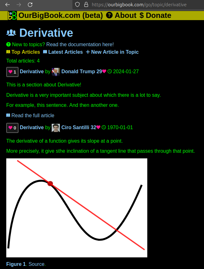
Figure 1. Screenshot of the "Derivative" topic page. View it live at: ourbigbook.com/go/topic/derivativeVideo 2. OurBigBook Web topics demo. Source. - local editing: you can store all your personal knowledge base content locally in a plaintext markup format that can be edited locally and published either:This way you can be sure that even if OurBigBook.com were to go down one day (which we have no plans to do as it is quite cheap to host!), your content will still be perfectly readable as a static site.
- to OurBigBook.com to get awesome multi-user features like topics and likes
- as HTML files to a static website, which you can host yourself for free on many external providers like GitHub Pages, and remain in full control

Figure 2. You can publish local OurBigBook lightweight markup files to either OurBigBook.com or as a static website.
Figure 3. Visual Studio Code extension installation.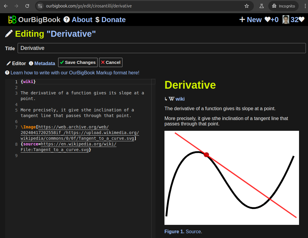
Figure 5. . You can also edit articles on the Web editor without installing anything locally. Video 3. Edit locally and publish demo. Source. This shows editing OurBigBook Markup and publishing it using the Visual Studio Code extension. 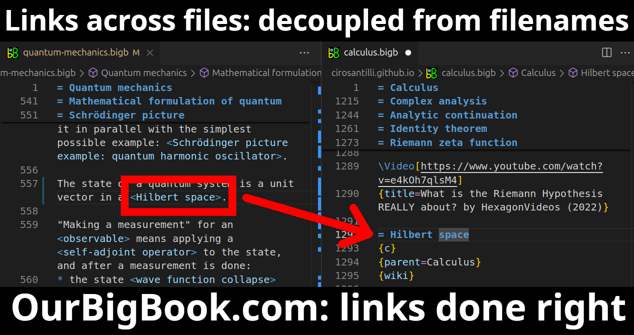
- Infinitely deep tables of contents:
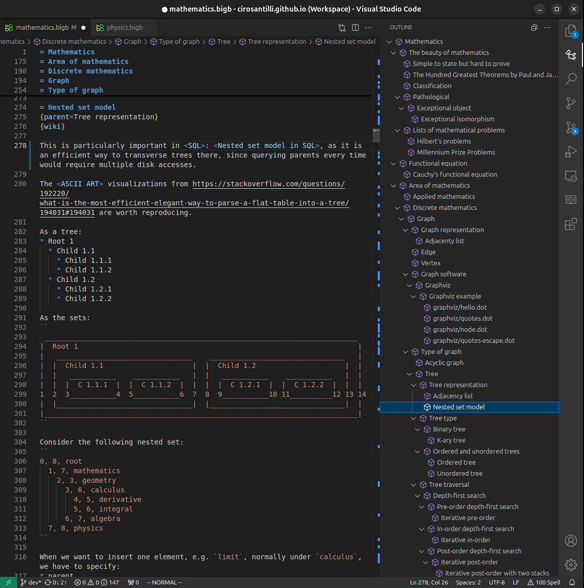

All our software is open source and hosted at: github.com/ourbigbook/ourbigbook
Further documentation can be found at: docs.ourbigbook.com
Feel free to reach our to us for any help or suggestions: docs.ourbigbook.com/#contact