
The transverse and longitudinal quantities characterize different correlations: spatial optical coherence across a wavefront and temporal optical coherence between delayed fields. Their numerical values require a convention for how much correlation counts as coherent.
Use a transparent reciprocal wave plate at its design wavelength. For the return calculation, assume a mirror at normal incidence with the same reflection coefficient for both transverse components; this is the usual ideal double-pass quarter-wave plate arrangement.
Take to mean that the mirror recedes along the incident plane electromagnetic wave. Put , with . The moving-mirror Doppler shift can be obtained directly by matching wave phase on the moving surface. Write the incident wave phase as and the reflected wave phase as , where and are positive wavenumbers. At the mirror, , the two phases must have the same time dependence; their constant offset incorporates the reflection phase shift. ThusConsequently the observed reflected angular frequency and ordinary frequency areThis is a redshift for a receding mirror and a blueshift for an approaching mirror. At small velocity, .
Equivalently, the relativistic Doppler effect gives in the mirror rest inertial frame. Reflection there reverses propagation and preserves frequency. Transforming the backward-going reflected wave to the laboratory gives another factor , so . A single Doppler factor would miss the effect of the return path.
Use a boost along the wire axis when comparing frames. The current variable in a four-current must be current density, in , rather than a scalar total current in amperes. For the wire-force calculation it is convenient to integrate charge and current over each cross-section and work with line quantities.
Use the ideal electrically short Hertzian dipole, , with negligible ohmic loss. Far-field statements additionally require an observation distance large compared with the wavelength and source dimensions. These assumptions distinguish its radiation from near-field coupling and from scattering by a general extended antenna structure.
The five tasks below concern a scanned Michelson interferometer. The original dashed curves are labelled visibility in arbitrary units; divide them by their maximum to obtain normalized interferometric visibility, which lies between zero and one.
Past exam of the optics and electrodynamics course of the University of Cambridge 2018 1 c Solution Created 2026-10-18 Updated 2026-10-20
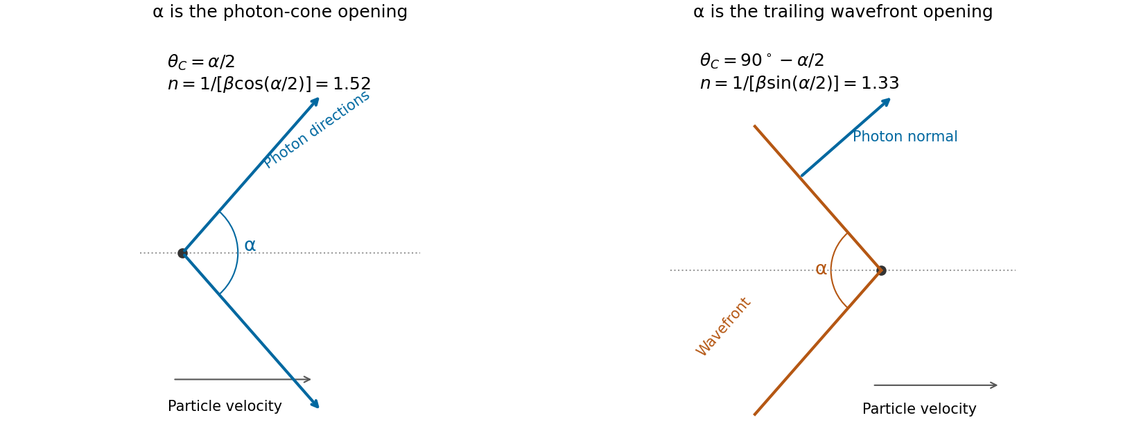
First obtain the particle speed from kinetic energy rather than treating as its total energy. With electron rest energy ,For Cherenkov radiation, the photon propagation direction makes angle to the particle trajectory, with . The speed correction is negligible at three significant digits, but the Cherenkov photon-cone and wavefront-cone angles must be distinguished.
If the given opening is the full cone of photon directions, . The result isIf instead denotes the full opening of the conical wavefront, its half-angle is complementary to the photon direction: . That convention givesThe original PDF supplies no cone diagram or definition distinguishing these geometries. Thus the literal full photon-cone interpretation gives , while follows from the wavefront interpretation. It would be incorrect to interchange sine and cosine without stating which cone is meant.
Past exam of the optics and electrodynamics course of the University of Cambridge 2018 1 b Solution 2026-10-18
At normal incidence, continuity of tangential wave phase makes both internal wavevectors normal to the parallel faces. For the ordinary wave in a uniaxial optical medium, the electric field is an eigenpolarization of the permittivity tensor, so . ThusIts energy path is also normal to the faces. The extraordinary wave differs because but need not be perpendicular to . In a nonmagnetic crystal, and is perpendicular to . The vectors lie in the same meridional plane, with and . Therefore the electric-displacement angle from birefringent walk-off equals the angular separation between and .
The observed lateral separation is accumulated over thickness , so . With and ,The two emergent rays are parallel because their outgoing wavevectors are both normal to the faces in air; their internal energy paths can nevertheless be displaced by birefringent walk-off. The angle quoted is the positive angle between the field vectors, so the unspecified lateral direction does not affect its value. The unpolarized light excites both eigenpolarizations; it does not require their energy paths to coincide.
Past exam of the optics and electrodynamics course of the University of Cambridge 2018 1 a Solution Created 2026-10-18 Updated 2026-10-20
The London penetration depth measures the density-to-mass ratio of carriers participating in superconducting screening. With electron-counted density and the stipulated bare electron mass ,Using , , and givesThis is the requested conduction-electron density within the assumed local London equation model. More precisely, it is the superconducting carrier density from London screening; identifying it with all conduction electrons assumes that they participate in screening at the measurement temperature. No temperature-dependent normal-carrier fraction is supplied.
Past exam of the optics and electrodynamics course of the University of Cambridge 2017 2 c Solution 2026-10-18
A charge moving uniformly through a transparent dielectric can emit Cherenkov radiation if its speed exceeds the phase velocity of light in that medium:It need not exceed the vacuum speed . The passing charge polarizes the medium; the induced response produces radiation that adds coherently along selected directions. Equivalently, phase matching along the trajectory requires . Since ,Here is the angle of the emitted light rays to the forward particle velocity: the rays form a cone around the track. With dispersion, both the threshold and cone angle depend on frequency; only transparent frequency bands satisfying the threshold contribute escaping radiation.
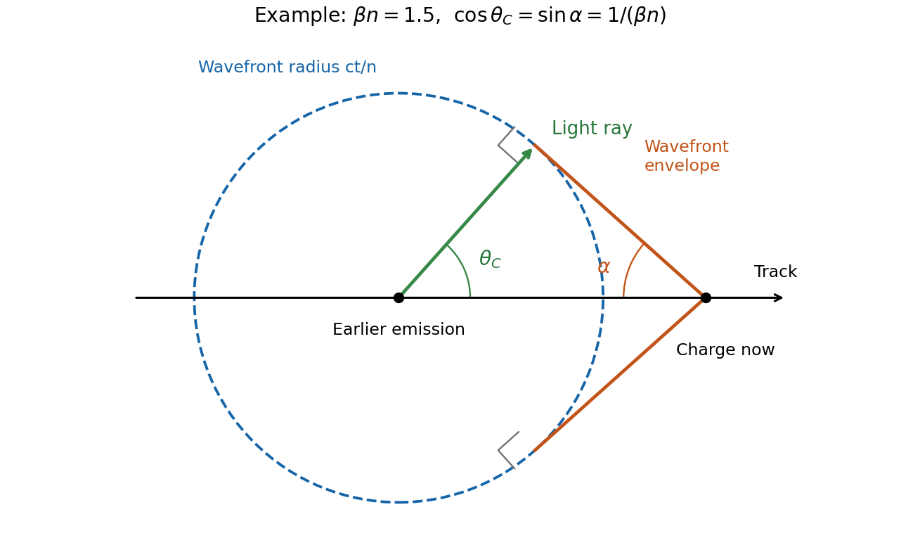


In the wavefront construction, a disturbance emitted a time earlier has radius , while the particle has moved . Tangents from the present particle position to these wavefronts make a backward-opening wavefront cone of half-angle , where . The light rays are normal to this cone. Consequently : the Cherenkov photon-cone and wavefront-cone angles are complementary, rather than identical.
Past exam of the optics and electrodynamics course of the University of Cambridge 2017 2 b Solution 2026-10-18
A phased array uses fixed antennas driven coherently, with adjustable electronic delays or phases. Changing those relative phases changes the direction of constructive interference.
For identical elements at , take time dependence and feed phase . In a far-field direction at angle from the array normal, the array factor isMultiply by the single-element antenna beam pattern to obtain the total angular intensity. All elements add in phase in the selected direction ifThus electronic control of steers the beam to without moving an element. Reciprocity gives the corresponding directionality in reception.
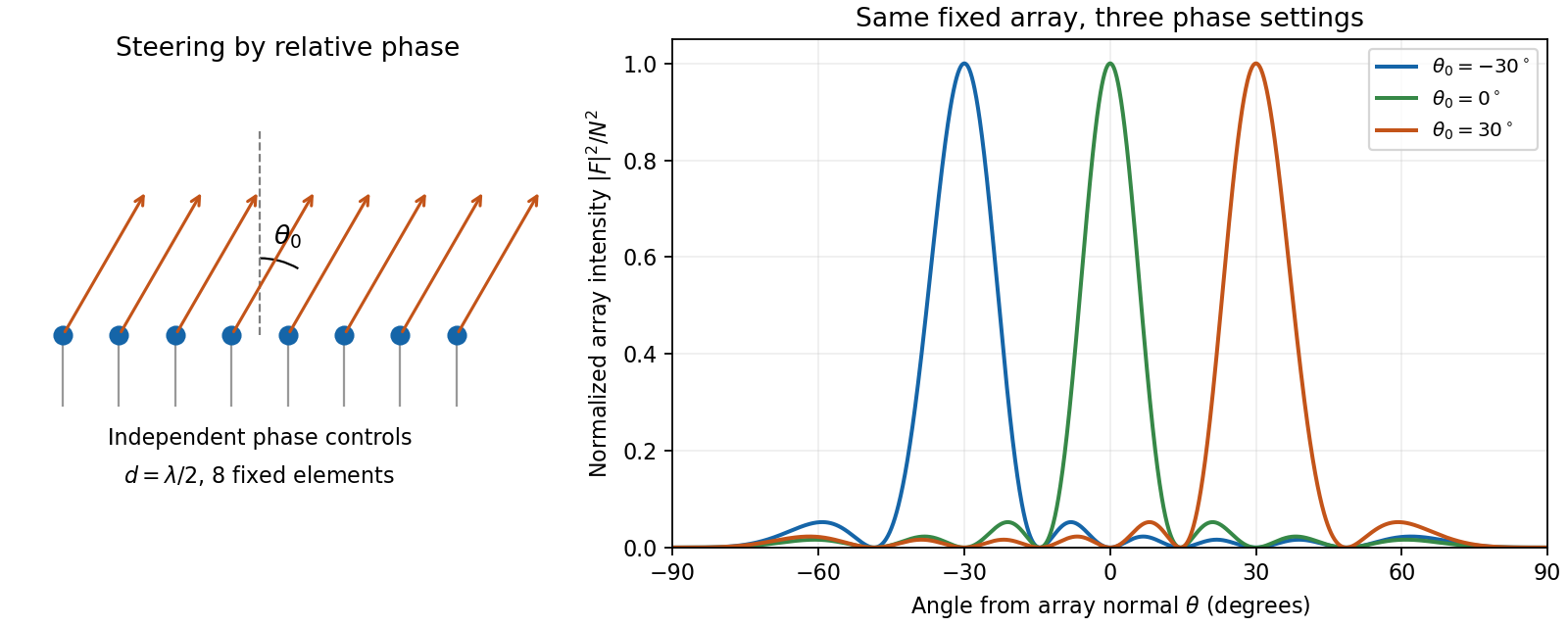
An electronically steered linear array and its normalized array factors
. Details. 
The aperture controls angular resolution: the nearest nulls obey , giving a main-beam width of order away from endfire. Additional equally strong maxima can occur when ; these are grating lobes. Choosing avoids them for all steering directions, with the usual limiting spacing. Amplitude tapering reduces side lobes at the cost of a wider main beam. For a broad frequency band, true time delays preserve steering more accurately than frequency-independent phase shifts.
Past exam of the optics and electrodynamics course of the University of Cambridge 2017 2 a Solution 2026-10-18
Molecules in clean air are much smaller than visible wavelengths. Their induced electric dipole moments undergo Rayleigh scattering. Away from molecular resonances, the induced dipole amplitude is approximately , with only weak wavelength variation in the polarizability . The radiation-zone electric field is proportional to , so the scattered intensity satisfiesThis is the Rayleigh scattering wavelength dependence. For equal incident intensities, light scatters about times as strongly as light. Thus light scattered out of the direct solar beam and into our line of sight is enriched in blue wavelengths.
The dipole mechanism also determines the Rayleigh scattering angular pattern. For unpolarized light, its angular factor is ; near scattering, the scattered light has strong linear polarization. The sky's perceived colour depends additionally on the solar spectrum, atmospheric transmission and the eye's spectral response, so the law alone does not predict a violet sky. Over a long near-horizontal path the direct beam loses more short-wavelength light, explaining red sunsets. Large aerosol particles instead produce Mie scattering, which is less strongly wavelength-selective and can make haze look whitish.
Past exam of the optics and electrodynamics course of the University of Cambridge 2017 1 c Solution 2026-10-18
Use axes adapted to the two orthogonal rotations in the diagram:For a linearly oscillating Hertzian dipole with real unit axis and total time-averaged radiated power , the angular distribution of electric dipole radiation isThe normalization follows from . Equal readings therefore implyHere , since otherwise all components would vanish. Reversing the axis is immaterial, so choose . The complete family isDefine , , and . Then , and the absolute intensity fixesFor the measured distance and intensity, the allowed axes and powers are:
- : , .
- or : , for either axis.
- : , .
The intensity data do not select a unique orientation or total power. This is the dipole-axis ambiguity from three intensity measurements: the readings constrain squared projections and lose their signs. For example, the first branch makes an angle with , but the other branches are equally consistent with the three measurements. A further suitable observation direction or polarization measurement is needed to remove the ambiguity. The calculation uses radiation-zone intensities, as appropriate to the Hertzian dipole model.
Past exam of the optics and electrodynamics course of the University of Cambridge 2017 1 b Solution 2026-10-18
Let be the intensity from either fibre alone at the observation point, assuming equal output intensities, matching polarizations and negligible drift. The screen samples the relative phase between the two outputs. For an ideal monochromatic laser, first-order optical coherence is complete andThe interference fringes are approximately equally spaced in the small-angle far field, with a slowly varying diffraction envelope. If the output separation is and the screen distance is , the interference fringe spacing is approximately . Equal phases at the two input ends do not ensure a central bright fringe: the extra fibre contributes carrier phase in addition to the free-space optical path difference.
For a finite linewidth, the time-averaged interference signal becomesHere may be defined for the slowly varying field envelope, with the carrier phase already included in . A realistic laser therefore gives reduced interferometric visibility; for , its extrema are and .
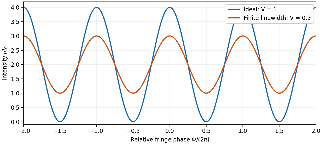
Ideal and finite-linewidth interference for equal output intensities
. Details. 
For a Lorentzian line shape of frequency full width at half maximum , temporal optical coherence givesThe relevant index is the group index. Using the intended nondispersive approximation ,This delayed-fibre linewidth measurement assumes the loss of contrast comes from linewidth. Unequal output intensities, polarization mismatch or mechanical phase fluctuations also lower interferometric visibility. If dispersion matters, the stated phase index alone does not specify the necessary group index.
Past exam of the optics and electrodynamics course of the University of Cambridge 2017 1 a Solution 2026-10-18
At an air–glass interface, resolve the incident unpolarized light into components perpendicular () and parallel () to the plane of incidence. The Fresnel equations give the parallel reflection coefficientAt Brewster's angle, . Together with Snell's law, this gives and . Thus, taking the incident medium to be air,The remaining reflected component has linear polarization perpendicular to the plane of incidence. This assumes a transparent, nonmagnetic glass with negligible absorption.
The symmetric group is generated by transpositions, each of order two. A group homomorphism to must map every transposition to zero, because the only target element annihilated by two is zero. Hence the map to is necessarily trivial.
For , the 3-cycles map to zero because their order divides three. All transpositions are conjugate group elements, and a map to an abelian group takes conjugate elements to the same value. That common value is either zero or one. Both choices work: they give the trivial map and the sign homomorphism, with an odd permutation sent to and an even permutation sent to .
A group homomorphism from the additive cyclic group is determined by the image of its generator , with the consistency condition in the target. Every element of either target satisfies this condition. ThereforeandThese formulas are well-defined because changing by six changes by a target multiple of its modulus. They list respectively two and three maps.
Choose . By Lagrange's theorem, its cyclic subgroup has order dividing the prime 101. It is not of order one, so . Thus the group is cyclic, and hence abelian. In particular, every pair of elements is , and .
A group homomorphism preserves the operation: for all . A group isomorphism is a bijective group homomorphism; its inverse also preserves the operation. The kernel of a group homomorphism is , a normal subgroup of .
Write the dihedral group as , where rotates through . There are six rotations and six reflections, so the order is 12. Conjugation by reverses a rotation, and conjugation by sends to . Consequently the conjugacy classes and their sizes areThe last two classes distinguish the reflection axes through opposite vertices and through opposite edge midpoints. Their sizes sum to 12.
There are unlisted articles, also show them or only show them.