
For ideal hard spheres, potential energy is zero for nonoverlapping configurations and infinite for overlaps. At fixed temperature and volume, the accessible fluid and crystal configurations therefore have no energetic preference of the ordinary bonding kind: the phase with larger entropy has lower Helmholtz free energy.
Ordering particle centers costs some configurational freedom, but at a high packing fraction it can give each particle more usable cage/free volume than a disordered crowded arrangement. The total number of allowed vibrational and positional configurations can then be greater in a crystal despite its visible long-range order. This is entropy-driven hard-sphere crystallization.
The crystal need not be at close packing. At the stated volume fraction near , substantial free space remains for thermal motion. Close packing near is the geometric upper bound for equal spheres, not the fraction at which the crystal first becomes thermodynamically favorable. Treating crystallization as an inevitable decrease in total entropy would confuse visible positional order with the full phase-space count.
The sedimentation scale height simplifies because the same drag coefficient controls both drift and diffusion:Applying the given criterion givesEquivalently, the gravitational Péclet number on the particle-radius scale is and must be at most one.
At the limiting radius is , corresponding to diameter approximately . Viscosity cancels from this equilibrium criterion, although it affects the time to approach equilibrium.
For the radius particle in part (i), and , about particle radii. It is therefore firmly diffusion-dominated on its own size scale. This does not mean uniform concentration over an arbitrarily tall vessel: the equilibrium density still decays on the finite scale . The supplied size criterion is an approximate gravity-versus-diffusion criterion, not a universal definition of every stable colloid.
At terminal speed the downward buoyant weight balances the Stokes drag:Positive gives downward settling; a lighter particle would rise. With , , and ,about , or per day.
The very small Reynolds number makes inertial corrections to Stokes flow negligible for an isolated particle. On short particle-scale distances, Brownian motion is much faster than this systematic drift. Nevertheless the nonzero settling speed can produce concentration gradients over sufficiently long times and large sample heights; Brownian motion does not cancel gravity.
The enlarged diamonds reach instead of . Subtract the unchanged charging contribution:Thus the two observed closed-orbital gaps are each approximately .
Define and , and choose the labels so . With two spins per orbital, the first two closed orbitals correspond to occupancies and . The lowest state is and the next is , soThe next orbital is , yielding the second observed gapThis ordering is self-consistent: , , and , as shown in the original level diagram.
Inside the rectangle the effective-mass Schrödinger equation iswith at all four walls because the confining potential is infinite outside. Separate . Each factor obeys a one-dimensional particle in a box equation. For ,so is proportional to with ; the zero and negative integers give no new physical states. The same argument applies in .
The normalized spatial states and their energies areThe product form and energy sum follow from separability. Each spatial orbital can accommodate two opposite-spin electrons under the stated spin degeneracy. These are single-particle confinement energies; the electrostatic charging contribution must still be added when interpreting transport addition energies.
The zero-bias gate period in the first plot is . In the constant interaction model, changing the gate-induced island charge by one electron givesThe tip is at above or below zero; use this half-height, not the full vertical extent. The addition energy is , giving
To distinguish the junction capacitances, explicitly adopt the circuit convention and . The diamond with zero-bias endpoints and has its positive tip near . Its two edge slopes are therefore and .
Writing the island electrochemical potential as a charge-dependent constant minus , alignment with the drain gives slope , while alignment with the source gives . ThusThe source/drain names are exchanged if the opposite lead is biased under the voltage convention. The figure alone establishes the pair unless that wiring convention is specified. Symmetric-looking diamond heights do not imply equal junction capacitances.
The pattern is characteristic of a single-electron transistor: a small conducting island is connected to source and drain by two tunnel junctions, and to a gate through a capacitance. Inside a Coulomb diamond, changing the island's integer charge costs more energy than the leads can supply, so sequential tunnelling is blocked. Outside it, an island electrochemical potential lies in the transport window and current can flow.
For clear Coulomb blockade, the island charging scale must exceed thermal broadening, and the tunnel junctions must be sufficiently resistive to preserve well-defined charge states:in the simplest circuit. Stray capacitances should be included in if appreciable. The gate changes electrostatic energy but should not provide a conducting leakage path. Lifetime broadening and cotunnelling should be small enough not to wash out the blocked regions.
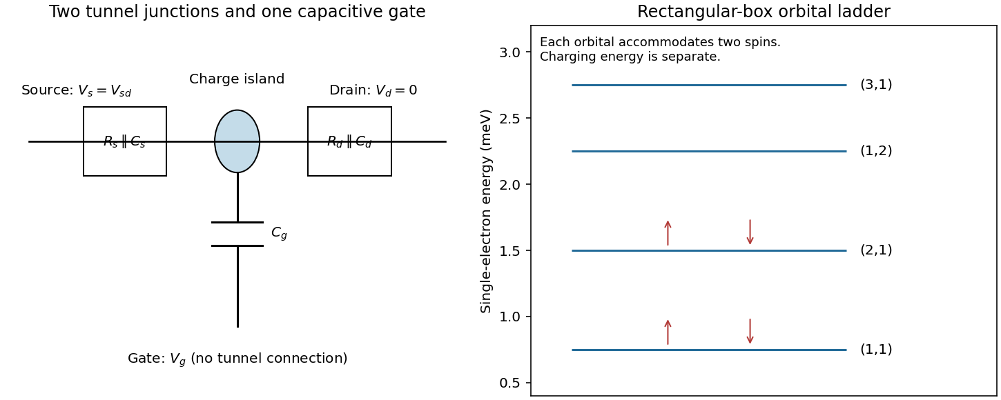

The almost identical unconfined diamonds are consistent with a constant interaction model having negligible or unresolved changes in single-particle level spacing.
In catalytic chemical vapor deposition, a metal nanoparticle activates a carbon-containing feedstock and supplies mobile carbon to the growing rim. Carbon can diffuse over the particle surface and, depending on the catalyst state, through its bulk. Once a curved carbon cap nucleates, continued incorporation extends the tube. Strong catalyst-support adhesion favors base growth; weaker adhesion can allow the particle to lift with the tube tip. A liquid catalyst is not universally required.
Particle size constrains tube diameter, but semiconducting character requires a particular wrapping family: . Merely making particles smaller does not select that congruence class. Routes toward predominantly semiconducting carbon nanotubes include controlling catalyst composition, exposed facets and size distribution to bias cap/rim nucleation and growth, or adjusting carbon chemical potential and growth/etching conditions so that metallic tubes are less likely to survive.
These are mechanistic strategies rather than a universal recipe. Experiments with catalyst conditioning found that high semiconducting selectivity depended sensitively on oxidizing/reducing gas conditions and came with a strong yield penalty, motivating a catalyst-deactivation model.[ref]
A phenomenological model for selective growth of semiconducting single-walled carbon nanotubes based on catalyst deactivation by Shunsuke Sakurai and others. Catalyst conditioning, gas composition and selectivity-yield tradeoff
The useful distinction is between selecting a structure at nucleation, selecting its growth rate, and selectively terminating or removing unwanted tubes. Each can enrich the semiconducting fraction, but they do not establish the same growth mechanism.
Write the reaction using the species actually supplied by solution. For either halide, a bulk contribution per converted formula unit isThe stated room-temperature feasibility means that the overall reaction free energy is negative under those conditions; it does not say that each microscopic step is downhill. Equal nominal concentrations also do not make iodide and bromide activities or solvation free energies identical.
At the nanoscale the balance additionally contains changing interfaces:Here is the number of converted formula units, and includes solvent-facing surfaces and contact with the titanium-dioxide support. Surface terms scale approximately as size squared whereas bulk terms scale as size cubed. Particle size, wetting, expansion during conversion and new grain interfaces can therefore shift both the conversion driving force and the nucleation barrier.
Microscopically, conversion requires desolvation, uptake of the organic cation and halide, redistribution through the precursor, and reorganization of the lead-halide framework. A study using these conversion conditions found energetically costly dispersed-ion intercalation for both compounds, with a much larger calculated penalty for MABr in PbBr than for MAI in PbI. The iodide's layered framework accommodates the cation more favorably; the bromide's undulated framework gives poorer coordination and greater local distortion. Stabilization on forming intermediate compounds and the final perovskite can nevertheless make the complete reaction favorable. The calculations are approximate energetic comparisons, not measured finite-temperature activation free energies.[ref]
Kinetics and energetics of metal halide perovskite conversion reactions at the nanoscale by Neha Arora and others. Fig. 4 and accompanying discussion: solvation reference, intercalation and conversion intermediates
Thus both reactions can be spontaneous yet proceed at very different rates: the same study observed faster MAPbI formation. One must distinguish net reaction free energy from intermediate penalties and diffusion barriers. Spontaneity alone supplies no quantitative ranking of the complete iodide and bromide reaction free energies.
- Can the precursor produce metal? Evaluate the reaction Gibbs free energy, including reduction, ligand exchange, precursor and reductant activities, solvation and byproducts. A nominal metal concentration is not the metal-atom chemical potential.
- What is the driving force for condensation? Compare the chemical potential of available metal species with that of the condensed phase. The resulting supersaturation supplies the bulk free-energy gain and competes with the surface cost of a critical nucleus.
- Where does it wet and nucleate? Let , and denote support-medium, particle-medium and support-particle interfacial free energies. For an isotropic cap, the contact angle through the particle obeys . This wetting balance determines the extent of substrate contact and the heterogeneous barrier.
- Which crystal faces survive? At fixed particle volume, minimize the sum of orientation-dependent surface and interface energies, plus any important strain or defect energy. For a free crystal, the Wulff construction gives facet distances proportional to their surface free energies. A Winterbottom construction incorporates the support interface and truncates the corresponding equilibrium shape.
Nucleation is the formation of a sufficiently large embryo of the new metallic phase. Producing metal atoms from dissolved precursor can create supersaturation; aggregation lowers bulk free energy but initially creates costly metal-medium interface. In the simplest spherical classical nucleation theory,where is the metal-medium interfacial free energy and is the bulk driving force per volume. Clusters below the critical size tend to redissolve; larger ones can grow.
In homogeneous nucleation, the critical cluster forms in the solution without a pre-existing interface: the initial products are free particles. In heterogeneous nucleation, a substrate, vessel wall or suspended seed replaces part of that costly new interface. For a spherical cap on a planar substrate,A wetting substrate therefore lowers the barrier; this assumes the same bulk driving force and isotropic interfacial energies.
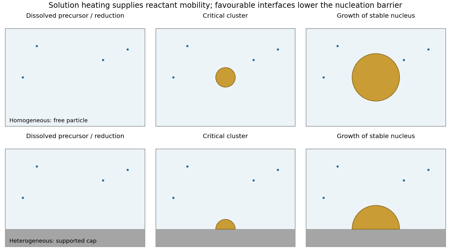

A final supported particle need not have nucleated heterogeneously: a free particle can nucleate in solution and later adsorb on the support. Conversely, a particle nucleated heterogeneously on a suspended seed can remain freely dispersed as a composite particle. Nucleation location and final support status are different classifications.
Microwave absorption heats the medium and possibly the support, changing reduction, diffusion and supersaturation. Preferential local heating can change the relative rates of the two routes. Microwave irradiation alone does not remove the thermodynamic nucleation barrier or demonstrate a special nonthermal mechanism.
Absorption converts part of the incident optical power into heat. Increasing laser power can therefore raise the local temperature, potentially driving a thermotropic nematic liquid crystal through its nematic-isotropic transition. The associated loss or change of orientational order, refractive index and anchoring can alter the trapping force or destabilize the trap.
Even below that transition, thermal gradients can induce convection, thermophoretic drift and changes in viscosity or Brownian fluctuations; sufficiently strong heating can damage the particle or host. Thus increasing laser power need not simply strengthen an otherwise unchanged optical trap.
Homeotropic anchoring means that the nematic director is locally normal to the particle surface, hence radial on a sphere. Far away, the uniform nematic liquid crystal has a fixed director , with and physically equivalent.
One plausible configuration is a quadrupolar Saturn-ring defect: the director is radial near the particle, bends into far away, and has a disclination loop just outside the particle's equator, in the plane perpendicular to . A meridional section cuts the loop at two points.
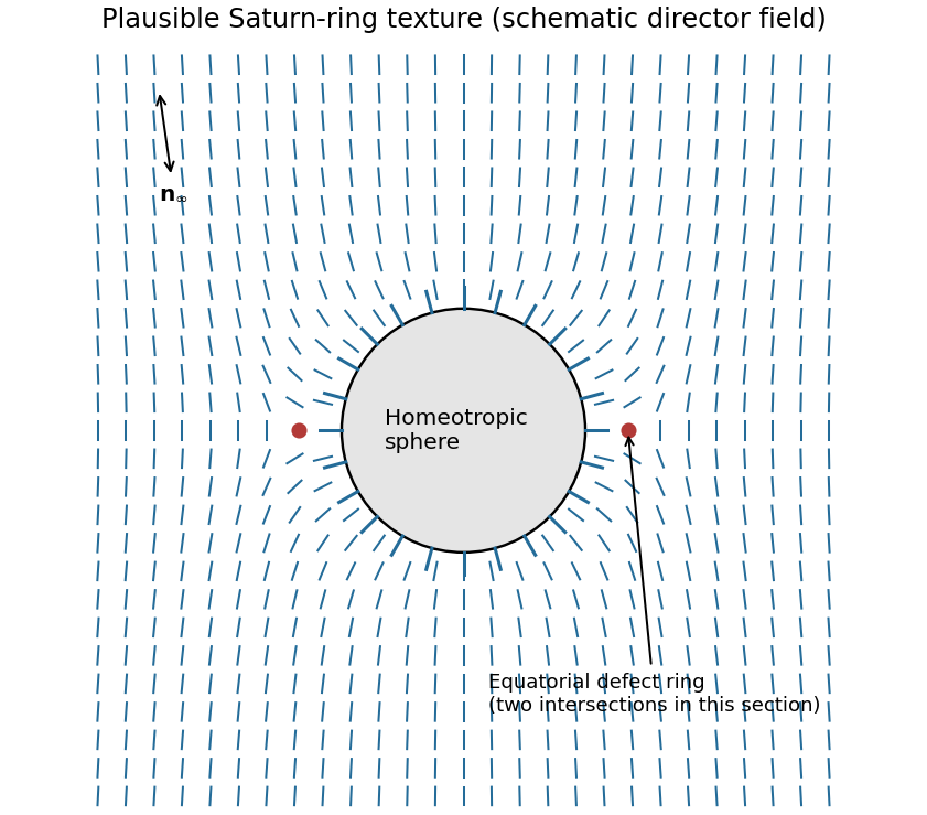

The defect compensates the topological distortion introduced by the radial surface boundary condition. A dipolar configuration with a nearby hyperbolic point defect is another possible texture. Which is stable depends on particle size, anchoring strength, elastic constants and external confinement; the boundary conditions alone do not uniquely select one.[ref]
Director field configurations around a spherical particle in a nematic liquid crystal by Holger Stark. Competing dipolar, Saturn-ring and surface-ring configurations
Because the sphere lies below the optical axis, a ray passing through its upper half samples a brighter part of the Gaussian beam than a comparable ray through its lower half. For a particle with higher refractive index than its surroundings, the stronger upper ray is deflected downward overall and transfers an upward reaction to the particle. The weaker lower ray gives a smaller downward reaction. Their transverse sum is therefore upward, toward the brighter axis.
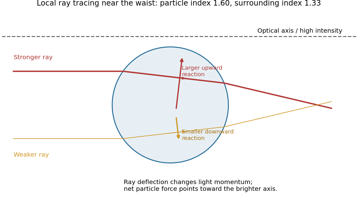
Unequal refracted rays give a transverse restoring force
. Original local ray tracing near a beam waist, with chosen refractive indices. The sphere is below the optical axis. The stronger ray contributes the larger upward reaction; the diagram isolates transverse restoration rather than reconstructing the examination figure. Source. Details.
If the displacement reverses, the force reverses, so the central position is transversely stable. Summing all the rays gives an optical gradient force toward the intensity maximum. There is also a forward optical scattering force. A tightly focused beam can have an axial restoring component that balances it, generally at a small displacement downstream of the ideal focus.[ref]
Observation of a single-beam gradient force optical trap for dielectric particles by Arthur Ashkin and others. Single-beam trapping by a sufficiently strong intensity gradient
Three-dimensional stability requires the restoring axial component to exceed the forward force over part of the trajectory. A Gaussian transverse intensity profile alone does not prove that condition; insufficient focusing can yield transverse confinement while the particle still moves downstream.
Refraction changes the propagation direction, and hence the momentum, of transmitted light. The particle receives the opposite momentum change by conservation of momentum. For a ray carrying power , a useful force scale iswith corrections for reflected rays and their momentum fluxes. Here is the surrounding refractive index; this is a ray-force scaling rather than a complete electromagnetic stress calculation.
For fixed geometry and refractive indices, , so the force contribution is proportional to the local intensity . Refraction toward the normal on entry and away from the normal on exit must both be included: a force inferred from only the first interface can have the wrong direction.
The specified size is larger than the wavelength, so a geometrical optics treatment is appropriate despite the generic “nanoparticle” label. A dipole/Rayleigh-particle formula would use the opposite size limit.
There are unlisted articles, also show them or only show them.