
The starting point is in the lamellar region. Preferential swelling of polystyrene makes polyisoprene the increasingly small minority domain, so the relevant effective composition moves left from .
If segregation stayed near , following the horizontal path in the supplied diagram would give lamellae → hexagonally perforated layers → hexagonally arranged PI cylinders → PI spheres, before sufficient asymmetry reaches the disordered region. The perforated-layer interval is narrow, around – at this segregation strength; precise boundaries should not be read more accurately than the figure allows.
Solvent also changes effective segregation, so the actual trajectory need not be horizontal. If it passes closer to the order-disorder boundary, it can enter the narrow double gyroid region instead of, or after, the hexagonally perforated layer phase. Greater dilution can cause disorder before all the ordered morphologies appear. Thus a plausible alternative is lamellae → gyroid → cylinders → disorder.
The robust prediction is the change toward minority-PI curved structures, not a guarantee that every named phase occurs. A solvent partition coefficient and a concentration-dependent interaction model would be needed to locate the actual path quantitatively; applying a dry-melt diagram to a swollen material is an effective approximation.
Reading the lowest point of the order-disorder boundary in the supplied experimental diagram gives approximately(about –, allowing for the graphical resolution). The ordered region just above that minimum is lamellar.
This is a reading of the supplied polyisoprene-polystyrene phase diagram. It should not be replaced by the often quoted symmetric-chain mean-field theory value : that refers to a different idealization and is not the minimum drawn here.
For the dry diblock copolymer, the block volume fractionis the volume assigned to the polyisoprene block divided by total polymer volume, not its mass fraction or the volume fraction of polymer in the whole solution. It controls domain curvature and topology. Similar block volumes favor alternating lamellae; a smaller minority block generally favors curved interfaces, cylinders and eventually isolated spherical domains.
The chemical block lengths are fixed. Temperature changes their volumes only through thermal expansion, so is often approximated as temperature independent; unequal expansion coefficients can produce a small change.
Solvent requires a distinction between dry composition and swollen domain composition. The dry remains fixed. If solvent volumes and partition into the two domains, an effective swollen fraction isA polystyrene-selective solvent therefore lowers , whereas a polyisoprene-selective solvent raises it. Equal proportional swelling leaves this effective ratio unchanged.
The Flory interaction parameter measures the free-energy penalty of unlike block contacts relative to like contacts, in units of . The degree of polymerization counts the reference segments per chain, using the segment-volume convention associated with . Their product, the block copolymer segregation strength , compares the tendency to avoid unlike contacts with the entropy cost of organizing and stretching connected chains.
At small , the diblock copolymer is disordered. Increasing can cause microphase separation: the blocks form distinct domains, but their covalent connection prevents complete macroscopic separation. Domain interfaces cost energy while chain stretching and lost configurations cost entropy; their competition selects a finite domain scale.
A common temperature law is , so increasing temperature often decreases segregation when . This is not a universal sign law for every polymer pair. For an intact, fixed chain, does not change just because temperature or solvent concentration changes.
Adding a nonselective good solvent usually dilutes unlike-block contacts and reduces an effective segregation strength; it does not chemically shorten the chain. A selective solvent additionally changes domain swelling and solvent-block interactions. One needs a ternary-mixture description, or a clearly defined effective , rather than treating the melt's as a universal solvent-concentration function.[ref]
Polyisoprene-polystyrene diblock copolymer phase diagram near the order-disorder transition by Ashish K. Khandpur and others. Definition of the segregation and composition variables and experimental phase behaviour
Two practical approaches retaining Co and NiFe are:
- Improve the spin-selective interfaces: control deposition and intermixing, avoid oxidation or magnetic dead layers, and reduce pinholes and spin-flip defects. The aim is large majority/minority transport asymmetry with low spin-memory loss, rather than merely the smallest total resistance.
- Optimize the Cu thickness and electrical stack: use the thinnest continuous spacer that still allows independent layer reversal and remains well below its spin diffusion length; reduce extraneous contact or lead resistance. This preserves a full antiparallel state and limits spin-independent dilution of the measured magnetoresistance ratio.
Increasing magnetic-layer thickness toward the useful spin-dependent-scattering scale can be another optimization, but growth beyond the relevant spin diffusion scale eventually gives diminishing returns. Merely increasing the bias current increases the readout voltage and possible heating; it does not, by itself, increase the intrinsic giant magnetoresistance ratio.
Roughness can produce a distribution of local switching fields and nonuniform reversal. The abrupt edges in the ideal pseudo spin valve loops then become rounded or sloping, the antiparallel plateau becomes less flat, and overlapping layer-reversal distributions can narrow or partly eliminate the clear high-resistance window. The middle panel of the original diagram illustrates only this broadening mechanism.
Correlated roughness on the two interfaces can also introduce orange-peel coupling, a magnetostatic coupling that favors parallel alignment. Such coupling shifts switching fields and can suppress independent reversal. Sufficiently severe roughness or pinholes can have a similar qualitative effect by directly coupling the ferromagnets.
Changes in amplitude require care. Some spin-dependent interface scattering contributes to giant magnetoresistance, so a small increase in roughness is not guaranteed to lower the signal monotonically. Intermixing, spin-flip scattering and an incompletely antiparallel state generally reduce useful contrast. The detailed width, displacement and height of therefore depend on how the interfaces become rough, rather than on a single roughness number.
Specify the magnetoresistance ratio as . Increasing a continuous Cu spacer adds spin-independent series resistance. Even when remains below the spin diffusion length, this dilutes the ratio; spin information need not be destroyed to reduce the percentage signal. In the illustrative two-current resistor model,which decreases as increases. The absolute difference also decreases in this model. At a fixed bias current, the measured voltage contrast is .
For comparable to or greater than the spin diffusion length, additional spin relaxation further suppresses the contrast. At the other extreme an ultrathin or discontinuous Cu layer can introduce direct magnetic coupling or pinholes, preventing a fully antiparallel state. Thickness-dependent interlayer coupling can therefore make the very-thin-spacer trend nonmonotonic; a universal exponential law does not follow from the supplied assumptions.
Assume NiFe is the softer layer, with , and that interlayer coupling is weak enough to permit separate reversal. Starting at large negative , both magnetizations point in the same direction and . During an increasing-field sweep:
- At , NiFe reverses while Co does not: the state is antiparallel and the resistance rises to .
- At , Co also reverses: the state becomes parallel and the resistance returns to .
On decreasing from positive saturation, the high-resistance window instead lies between and . Thus the two sweep directions give displaced rectangular high-resistance windows, not a single reversible resistance peak centered on zero.
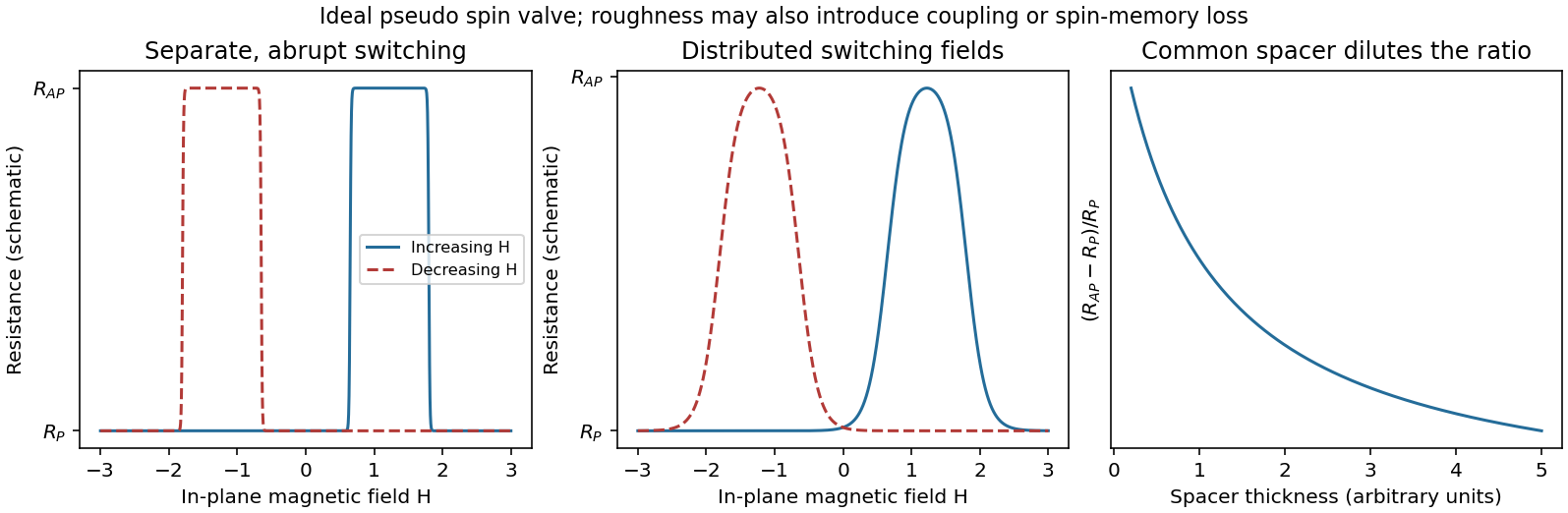
Pseudo spin-valve resistance loops, distributed switching and spacer dilution
. Original illustrative curves. Separate coercive fields create an antiparallel window on each sweep. The middle panel isolates switching-field broadening; its retained peak height is not a claim that real roughness leaves the GMR amplitude unchanged. Source. Details.
If Co were the softer layer, the sequence of layer labels would be exchanged. A continuous spacer and sufficiently weak coupling are additional assumptions: negligible surface roughness alone does not guarantee independent switching at every Cu thickness.
The giant magnetoresistance mechanism is spin-dependent conduction through the two ferromagnets. Exchange splitting gives majority and minority bands different density of states values at the Fermi energy. Scattering into those bands, together with interface scattering, produces different resistances for the two spin channels. The relevant quantity is the spin-dependent transport/scattering rate, not simply a count of all available states.
For parallel layer magnetizations, one global spin channel encounters relatively weak scattering in both Co and NiFe, providing a low-resistance path. For antiparallel magnetizations, each global spin channel encounters one more strongly scattering ferromagnet, so both paths are comparatively resistive. The channels conduct in parallel while each crosses the layers in series. This is current-perpendicular-to-plane magnetoresistance, because the current crosses the interfaces.[ref]
Nobel Lecture: Origin, development, and future of spintronics by Albert Fert. Spin-dependent conduction and the distinction between CPP and CIP transport
In the simplest two-current resistor model, with equal magnetic layers having channel resistances and spacer resistance per channel,Real Co/NiFe layers need not have equal parameters, but the same-sign spin asymmetries normally give . Their different magnetic coercivities allow the two configurations to be selected separately.
Using the magnitude of the classical slope,The Landau filling factor at isUnder the convention that the “last Landau level” means the last resolved spin branch, its degeneracy per area is . Setting givesAbove this threshold all carriers fit into that lowest resolved branch, which is partially filled when .
On an integer plateau the sheet transverse resistivity has magnitudewhere the integer counts occupied resolved quantum Hall edge states. Increasing at fixed sheet density reduces the Landau filling factor . The observed trace is therefore a staircase toward larger , with transitions between plateaux rather than the classical straight line. In the plateau regions ; dissipative peaks occur at transitions.
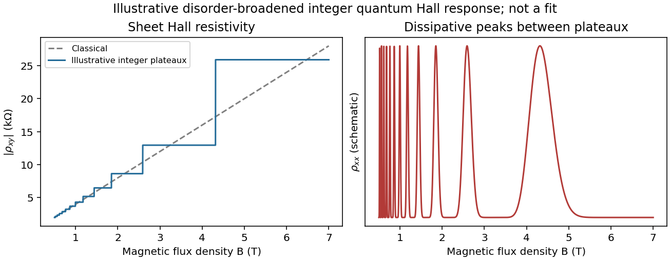
Classical Hall line and illustrative integer quantum Hall plateaux
. Original schematic responses, with the classical slope fixed by the later calculation. Plateau widths and dissipative peak shapes are illustrative rather than fitted to an experimental trace. Source. Details.
It is not correct to demand an exactly integer value of everywhere along a finite-width plateau. Localization accommodates changes in total population without changing the number of extended current-carrying channels. If spin remains unresolved, the usual spin-degenerate sequence contains even integers rather than every integer.
The integer quantum Hall effect requires a conducting two-dimensional electron gas with well-resolved Landau levels. In the simple parabolic-band model their orbital spacing isLow temperature and sufficiently low disorder broadening are needed so that and the relevant level width are small compared with this spacing. A high-mobility sample with is therefore useful.
Some disorder has a constructive role: localized states between extended Landau-level states allow the Fermi energy to move through a range of carrier populations while the transport response stays on a plateau. The longitudinal response is then very small and the transverse response is quantized. Whether odd or only even integer plateaux are resolved also depends on whether spin splitting is resolved.
In the classical single-carrier model,for a two-dimensional sheet. The curve is a straight line through the origin, with its sign determined by the carrier charge and the voltage convention. The sheet Hall coefficient has units , consistent with the numerical slope used later.
The classical transverse response is not quantized. With carrier density and scattering parameters fixed, reversing reverses the transverse signal. Several carrier populations can produce a nonlinear classical curve, so straight-line behaviour here uses the stated single-population approximation rather than being a property of every conductor.
Take a two-dimensional conducting sheet in the plane with magnetic flux density and electric current density along . Moving carriers feel the transverse Lorentz force . They accumulate at opposite edges, producing a transverse electric field until its force balances the magnetic deflection:For the transverse-voltage convention , this gives andThe Hall effect therefore measures carrier sign as well as density in the single-carrier approximation: electrons give the opposite transverse-voltage sign from positive carriers. Some tensor conventions call rather than ; the physical sign is fixed by the stated lead and field directions.
The Hall voltage is the integral of this transverse electric field across the sample width. In a three-dimensional slab of thickness , its magnitude is ; for a sheet, use the sheet number density and omit .
An atomic layer deposition recipe depends on the surface chemistry during the first cycles. A silicon wafer normally carries native oxide with reactive hydroxyl groups. A pristine graphene basal plane has no comparable dense population of dangling bonds or hydroxyl groups, so precursor adsorption and initial nucleation are much less uniform.
Consequently the nominal number of cycles calibrated to give on silicon can instead give isolated alumina islands, preferential decoration of edges, grain boundaries and defects, and uncovered graphene between islands. Adsorbed transfer residues may provide additional, irregular nucleation sites. Once alumina has nucleated, later cycles grow on the alumina normally; the problem is delayed, spatially uneven nucleation. The resulting local island height can exceed the film's area-averaged equivalent thickness.[ref]
Atomic layer deposition of metal oxides on pristine and functionalized graphene by Xinran Wang and others. Pristine graphene nucleation at edges and defects, and uniform growth after noncovalent functionalization
Two suitable improvements are:
- Introduce a dense, controlled nucleation layer, for example a noncovalently adsorbed functional layer carrying reactive groups or a very thin oxidized metal seed. This supplies precursor-binding sites while limiting damage to the conducting carbon network.
- Optimize initial exposure rather than reuse the silicon recipe unchanged: use longer precursor residence/soak times and suitably reduced initial temperature to increase adsorption and nucleation, then continue normal cycles after closure. Direct sub- continuous growth with extended residence times has been demonstrated.[ref]Parameter space of atomic layer deposition of ultrathin oxides on graphene by Adrianus I. Aria and others. Pulse/residence-time control of initial nucleation and continuous ultrathin films
Ozone or a mild plasma is another possible activation route, but it must be controlled because creating covalent defects can degrade the electrical properties that motivate using graphene.
The gas impingement flux onto a surface follows from the normal component of the Maxwell-Boltzmann distribution:Here and , givingAssume a conventional monolayer density and unit sticking coefficient. The incident-monolayer time isThus a few milliseconds is the usual contamination-time estimate at this pressure.
The assumed molecular footprint matters: neither nor the sticking coefficient is specified. More generally if the sticking probability is and desorption is negligible. Water can desorb rapidly from clean graphene at room temperature, so the incident-monolayer estimate does not establish that a stable, complete water layer actually forms in that time. Residues and defects can increase local adsorption.
Two layers need not have the same electronic structure everywhere. Different rotational alignments create domains of twisted bilayer graphene; AB-stacked regions instead have the usual coupled low-energy bilayer bands. In a twisted domain, displaced Dirac cones hybridize where they meet, producing avoided crossings and saddle points in the two-dimensional dispersion relation. The resulting Van Hove singularities enhance optical transitions at energies that depend on the twist angle. Different domains therefore absorb different parts of the visible spectrum and can show different colours despite having the same layer count.[ref]
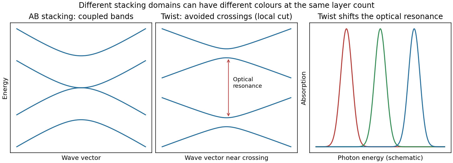
Bilayer stacking changes the bands and optical absorption
. Original illustrative bands: AB-stacked bands, a local cut through avoided crossings in a twisted domain, and schematic angle-dependent absorption peaks. The middle panel is a local cut, not the entire two-dimensional band structure. Source. Details.
On a silicon/silicon-dioxide substrate, reflected beams from the film stack also interfere. The wavelength-dependent optical response of the bilayer graphene changes this reflected contrast, making the domain differences visible. The observation is consistent with stacking domains; colour alone does not uniquely prove a twist angle. Variations in oxide thickness, trapped contamination, folds or local doping can also change contrast and should be checked independently, for example by Raman spectroscopy.
There are unlisted articles, also show them or only show them.